
TMT84 Temperature Transmitter Address Setting Overview
The TMT84 temperature transmitter supports the HART communication protocol, and its address setting directly affects device identification and communication in the bus network. Correct address configuration is a prerequisite for ensuring normal interaction between the transmitter and the control system. Based on official technical documentation, this article outlines the complete process and key points of address setting.
Preparation Before Address Setting
Before operation, please confirm that the following conditions are met to avoid setting failure or equipment damage.
- The transmitter is powered off, and ensure the working environment meets explosion-proof requirements (if applicable).
- Prepare suitable tools, such as a small flathead screwdriver, for toggling the switches.
- Consult the device manual to confirm the target address range (usually 1~63, depending on network size).
- Record the current address so it can be restored if needed.
TMT84 Address Setting Steps
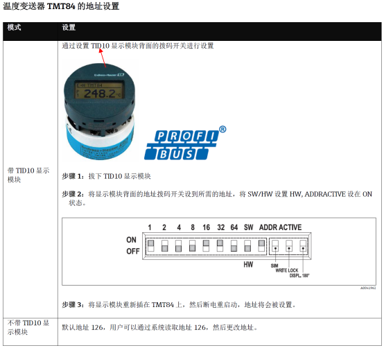
Address setting is performed through the DIP switch inside the transmitter, and operation must be done carefully. Please follow the steps below:
- Disconnect the transmitter power supply and wait at least 30 seconds to ensure the internal capacitor is fully discharged.
- Open the transmitter housing and locate the DIP switch group on the electronic module (usually 8 positions).
- According to the target address, set the ON/OFF state of each switch with reference to the table below. The address is determined by binary encoding, with switch 1 as the least significant bit (LSB) and switch 8 as the most significant bit (MSB).
- After setting is complete, reassemble the housing and power on.
- Use a HART communicator or configuration software to read the transmitter address and confirm that the setting has taken effect.
Address DIP Switch Reference Table
The table below lists the switch states corresponding to common addresses (1=ON, 0=OFF), showing only the lower 6 bits; the upper 2 bits are usually kept OFF.
| Target Address | Switch 1 | Switch 2 | Switch 3 | Switch 4 | Switch 5 | Switch 6 |
|---|---|---|---|---|---|---|
| 1 | 1 | 0 | 0 | 0 | 0 | 0 |
| 2 | 0 | 1 | 0 | 0 | 0 | 0 |
| 3 | 1 | 1 | 0 | 0 | 0 | 0 |
| 4 | 0 | 0 | 1 | 0 | 0 | 0 |
| 5 | 1 | 0 | 1 | 0 | 0 | 0 |
| 10 | 0 | 1 | 0 | 1 | 0 | 0 |
| 20 | 0 | 0 | 1 | 0 | 1 | 0 |
| 63 | 1 | 1 | 1 | 1 | 1 | 1 |
Precautions for Address Setting
To ensure stable communication, please pay attention to the following points:
- Address uniqueness: In the same HART network, each transmitter address must be unique; otherwise, communication conflicts will occur.
- Power restart: After changing the address, power must be cycled for the new address to take effect.
- Explosion-proof areas: When operating in hazardous areas, be sure to comply with local explosion-proof regulations; opening the cover while energized is prohibited.
- Parameter backup: It is recommended to record other configuration parameters before changing the address to avoid accidental loss.
Address Verification and Troubleshooting
After setting is complete, verify whether the address is correct using the following methods:
- Use a HART communicator to connect to the transmitter and enter the communication menu to view the device address.
- Check on the control system side whether the device at that address can be polled normally.
- If communication fails, check whether the DIP switch contact is good, or try setting it again.
If the problem persists, please refer to the TMT84 technical manual or contact the supplier's technical support.