
TMT82 Temperature Transmitter Wiring Overview
TMT82 temperature transmitter is a HART smart temperature transmitter commonly used in industrial sites, supporting various sensor inputs such as resistance temperature detectors (RTD) and thermocouples (TC). Correct wiring is the prerequisite for ensuring measurement accuracy and long-term stable operation.
Combined with physical wiring diagrams, this article introduces the terminal definitions, typical wiring methods, and precautions for the TMT82, for reference by engineering technicians and procurement personnel.
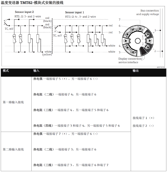
TMT82 Terminal Definitions and Identification
Before wiring, the transmitter nameplate model and wiring terminal numbers should be confirmed first. The TMT82 usually uses screw-type wiring terminals, and the terminal numbers correspond one-to-one with their functions.
Common Terminal Functions
- Sensor input terminals: used to connect RTD or thermocouple signal wires.
- Power supply and signal output terminals: two-wire loop, where power supply and 4-20mA signal share a pair of wires.
- Grounding terminal: used for shielding layer or enclosure grounding to suppress interference.
Before wiring, be sure to disconnect power and check the terminal numbers to avoid mistakenly connecting power to the sensor terminals and causing damage.
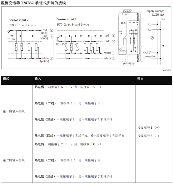
TMT82 Typical Wiring Methods
The TMT82 supports two-wire and four-wire wiring configurations, depending on the sensor type and on-site power supply conditions. The following are common wiring steps.
Two-Wire Wiring Steps
- Confirm that the power supply is DC 24V and is in the power-off state.
- Connect the positive pole of the power supply to the transmitter + terminal, and the negative pole to the - terminal.
- The 4-20mA signal and power supply share the same loop, and the load resistor is connected in series in the loop.
- After checking that the wiring is secure, power on and observe whether the output current is normal.
Four-Wire Wiring Steps
- Connect the sensor signal wires to the corresponding input terminals respectively, paying attention to positive and negative polarity.
- Connect the power supply separately to the power supply terminals, and connect the signal output to the acquisition device.
- Ground the shielding layer at one end to reduce electromagnetic interference.
- After power-on, check whether the measured value is consistent with the actual temperature.
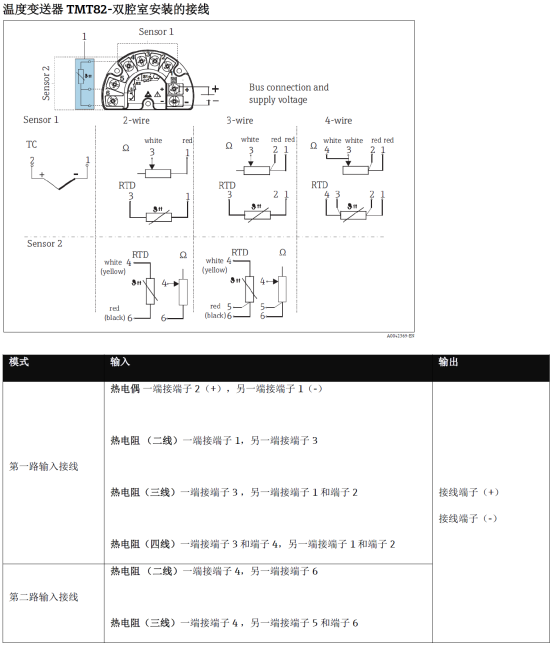
Wiring Method Comparison and Parameter Reference
Different wiring methods differ in power supply, signal, and anti-interference capability. The following table can be referenced during selection and construction.
| Wiring Method | Power Supply Method | Signal Output | Applicable Scenarios |
|---|---|---|---|
| Two-wire | Loop-powered DC 24V | 4-20mA | Conventional on-site measurement, simple wiring |
| Four-wire | Independent power supply | 4-20mA/voltage | High precision, high anti-interference requirements |
Wiring Precautions
- Before wiring, be sure to disconnect power to prevent short circuits or damage to the transmitter.
- Use shielded cables, and ground the shielding layer at one end to avoid ground loop interference.
- The lead resistance of the sensor should be as small as possible. For RTD, three-wire compensation is recommended.
- After power-on, check whether the 4-20mA output corresponds to the temperature, and calibrate with a HART communicator if necessary.
- The wiring terminals should be tightened to prevent signal fluctuations caused by looseness.
Following the above wiring specifications can effectively improve the measurement accuracy and operational reliability of the TMT82 temperature transmitter.