
TMT84 Temperature Transmitter Wiring Overview
The TMT84 temperature transmitter is a commonly used temperature measurement instrument in industrial sites. Correct wiring directly affects measurement accuracy and system stability. This article will introduce the wiring method, terminal definitions, and precautions of the TMT84 in detail to help engineering technicians quickly complete installation.
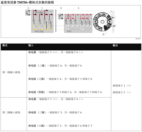
Terminal Description
The TMT84 usually uses a dual-chamber housing, and the terminals are located on the electronic chamber side. The terminal definitions are shown in the following table:
| Terminal Number | Function | Description |
|---|---|---|
| 1 | Power Positive (+) | Connect to the positive pole of the 24V DC power supply |
| 2 | Power Negative (-) | Connect to the negative pole of the 24V DC power supply, also used as the 4-20mA signal loop |
| 3 | Sensor Input (+) | Connect to the positive end of the RTD/thermocouple |
| 4 | Sensor Input (-) | Connect to the negative end of the RTD/thermocouple |
Note: The specific terminal numbers may vary slightly depending on the model version. Please refer to the product nameplate or manual.
Wiring Steps
- Power off: Ensure the power is turned off to avoid electric shock or damage to the transmitter.
- Open the housing: Unscrew the electronic chamber cover to expose the terminals.
- Connect power and signal wires: Connect the positive pole of the 24V DC power supply to terminal 1, and the negative pole to terminal 2. If 4-20mA output is used, the signal wire is also led out from terminal 2 to the control system.
- Connect the sensor: According to the sensor type (RTD or thermocouple), connect the signal wires to terminals 3 and 4. For a three-wire RTD, an additional compensation wire is required.
- Check and tighten: Confirm that all wiring is secure, with no short circuit or open circuit.
- Restore power: Close the housing, turn on the power, and observe whether the transmitter works normally.
Wiring Precautions
- Power polarity: Reversing the power supply is strictly prohibited, otherwise the transmitter may be damaged.
- Signal isolation: If there is strong electromagnetic interference on site, it is recommended to use shielded cables and ground the shield at one end.
- Sensor matching: Ensure that the transmitter configuration matches the sensor type (such as Pt100, K-type thermocouple, etc.).
- Environmental protection: After wiring is completed, ensure the housing is sealed to prevent moisture or dust from entering.
- Explosion-proof occasions: When used in hazardous areas, explosion-proof regulations must be followed, and intrinsically safe or flameproof wiring methods must be used.
Common Problems and Troubleshooting
No Output Signal
- Check whether the power supply is normal and the polarity is correct.
- Check whether the sensor is damaged or the wiring is loose.
- Confirm whether the transmitter configuration is correct.
Output Signal Fluctuation
- Check whether the shielded wire is properly grounded.
- Eliminate nearby strong interference sources.
- Check whether the sensor wiring is secure.
Summary
Correct wiring is the foundation for reliable operation of the TMT84 temperature transmitter. Following the above steps and precautions can effectively avoid common faults and ensure measurement accuracy. For more detailed configuration and commissioning information, please refer to the product manual or contact technical support.