
RSG30 Wiring Overview
The RSG30 instrument uses screw or spring terminal blocks. All connectors are polarity-protected to ensure safe and reliable wiring. Wiring is simple and quick; use a size 0 screwdriver to open the spring terminals.
Terminal Types and Cable Specifications
Spring Terminals
- Applicable signals: digital I/O signals, RS485 signals, analog input signals
- Maximum wire cross-sectional area: 1.5 mm² (14 AWG)
- Maximum cross-sectional area for relay connection wires: 2.5 mm² (13 AWG)
- Stripping length: 10 mm (0.39 in)
Screw Terminals
- Applicable signals: power supply signals
- Maximum wire cross-sectional area: 2.5 mm² (13 AWG)
- Stripping length: 6 mm (0.24 in)
Wiring Precautions
When wiring, select the correct terminals according to the signal type and ensure the wire gauge meets specifications. After opening the spring terminal with a screwdriver, insert the conductor and confirm it is secure.
Wiring Diagram
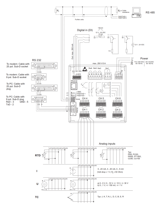
The following figure shows the typical wiring layout of the RSG30, including power, signal, and sensor connections.
Sensor Auxiliary Voltage Output Wiring
Two-Wire Sensors
The auxiliary power supply can power two-wire sensors. The wiring method is shown in Figure 5.
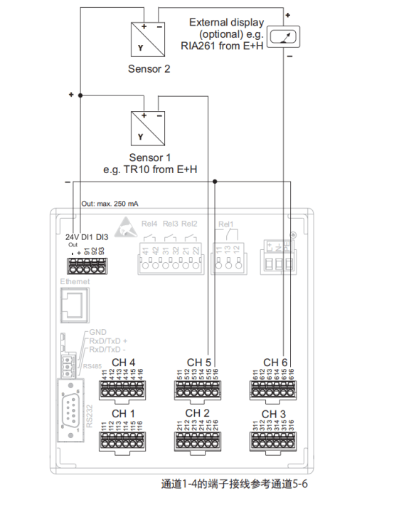
Figure 5: Auxiliary power supply powering a two-wire sensor (within current range)
Four-Wire Sensors
For four-wire sensors, the auxiliary power supply wiring is shown in Figure 6.
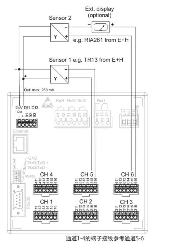
Figure 6: Auxiliary power supply powering a four-wire sensor (within current range)