
RSG40 Wiring Overview
RSG40 wiring adopts a modular design and supports multiple sensor types and signal outputs. All connectors behind the instrument are threaded or spring terminal blocks with polarity protection, ensuring convenient and quick connection. Correct wiring is the foundation for ensuring measurement accuracy and equipment safety.
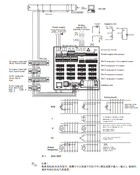
Sensor Auxiliary Voltage Output Wiring
RSG40 can provide auxiliary voltage output for 2-wire or 4-wire sensors. Select the corresponding wiring method according to the sensor type to ensure the signal loop is correct.
2-Wire Sensor Wiring
2-wire sensors share two wires for power supply and signal, and polarity must be observed during wiring. The auxiliary voltage output terminal provides operating power to the sensor while receiving the current signal.
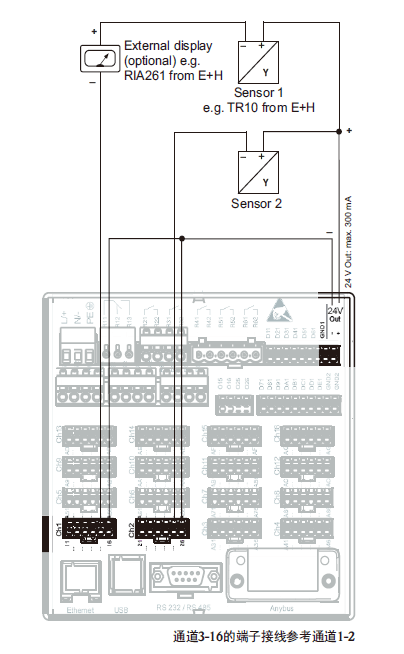
4-Wire Sensor Wiring
4-wire sensors separate power supply and signal, and the power supply positive and negative and signal positive and negative must be connected separately during wiring. The auxiliary voltage output terminal supplies power to the sensor independently, and the signal terminals are connected to the instrument.
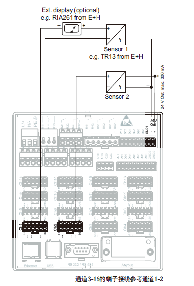
Cable Specifications and Spring Terminals
RSG40 uses spring terminals, allowing quick connection without screws. Use a size 0 screwdriver to open the spring terminal, insert the conductor, and release to lock it. During wiring, select the appropriate wire diameter according to the signal type.
Wiring Wire Diameter and Stripping Length Requirements
Different signal types have clear requirements for conductor cross-sectional area and stripping length. The specific parameters are shown in the table below.
| Connection Type | Terminal Type | Maximum Wire Diameter | Stripping Length |
|---|---|---|---|
| Digital I/O, RS485, analog input | Spring terminal | 1.5 mm² (14 AWG) | 10 mm (0.39 in) |
| Power supply signal | Threaded terminal | 2.5 mm² (13 AWG) | 6 mm (0.24 in) |
| Relay | Spring terminal | 2.5 mm² (13 AWG) | 10 mm (0.39 in) |
Wiring Operation Steps
Follow the steps below to ensure firm and reliable wiring:
- Confirm that the power supply is disconnected to avoid live operation.
- Strip the conductor insulation according to the wiring type, and ensure the stripping length meets the requirements in the table above.
- Insert a size 0 screwdriver into the spring terminal release hole to open the terminal.
- Insert the exposed conductor fully into the terminal hole, remove the screwdriver, and the terminal will lock automatically.
- Gently pull the conductor to confirm that the connection is firm and not loose.
Wiring Precautions
- All connectors have polarity protection; reverse connection will not damage the instrument, but the signal may be abnormal.
- Digital I/O, RS485, and analog input signals must use spring terminals, with a wire diameter not exceeding 1.5 mm².
- Power supply signals use threaded terminals, with a wire diameter not exceeding 2.5 mm² and a stripping length of 6 mm.
- Relay outputs use spring terminals, with a wire diameter not exceeding 2.5 mm² and a stripping length of 10 mm.
- After wiring is completed, check whether all terminals are tightened to avoid measurement errors caused by poor contact.