
TMT162 Temperature Transmitter Wiring Overview
The TMT162 temperature transmitter is a commonly used temperature measurement instrument in industrial sites, and the quality of its wiring directly affects measurement accuracy and signal stability. Correct wiring requires clarifying terminal functions, power supply methods, and signal loop types. This article focuses on the wiring key points of the TMT162 to help engineering technicians and procurement personnel quickly master it.
Preparation Before Wiring
Tools and Materials
- Shielded cable meeting specifications
- Screwdriver and wire stripper
- Multimeter (for continuity and voltage checks)
- TMT162 product manual and terminal wiring diagram
Safety Precautions
- Be sure to cut off the power supply before wiring to avoid live operation.
- Confirm that the on-site environment meets the instrument's protection rating requirements.
- Avoid laying cables in parallel with power lines to reduce electromagnetic interference.
Terminal Definitions and Wiring Methods
Terminal Function Description
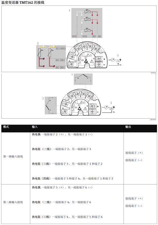
The TMT162 usually has power terminals, signal output terminals, and sensor input terminals. Terminal numbering may vary slightly among different models; the physical labels and manual shall prevail.
| Terminal Type | Function | Typical Marking |
|---|---|---|
| Power terminal | Connect supply voltage | + / - |
| Signal terminal | Output 4-20mA signal | OUT+ / OUT- |
| Sensor terminal | Connect RTD or thermocouple | 1 / 2 / 3 / 4 |
Two-Wire Wiring Steps
- Connect the positive pole of the power supply to the transmitter's positive terminal.
- Connect the signal line in series with the load and then back to the negative pole of the power supply to form a closed loop.
- After confirming the polarity is correct, power on and measure the loop current with a multimeter.
Four-Wire Wiring Steps
- Connect the positive and negative poles of the power supply to the corresponding power terminals.
- Lead out the positive and negative poles of the signal independently to the acquisition device.
- Connect the sensor to the input terminals according to its type; note that a three-wire RTD requires a compensation wire.
Common Wiring Problems and Troubleshooting
- No signal output: Check whether the power polarity and supply voltage meet requirements.
- Large signal fluctuation: Check the shielding layer grounding and interference sources.
- Measurement deviation: Confirm that the sensor wiring method is consistent with the graduation setting.
After completing the wiring, it is recommended to perform zero and span calibration to ensure that the TMT162 output matches the actual temperature before putting it into formal operation.