
What Is a Vortex Flowmeter
A vortex flowmeter is a velocity-type flow measurement instrument based on the Kármán vortex street principle, mainly used to measure the volumetric flow of liquids, gases, or steam. With features such as no moving parts, high reliability, and wide applicability, it is widely used in industrial process measurement.
I. Working Principle
1. Kármán Vortex Street Phenomenon
When fluid flows through a bluff body in a pipeline (such as a cylinder, triangular prism, etc.), two alternating asymmetric rows of vortices are generated downstream of the bluff body. These vortices are arranged like streetlights on both sides of a street, known as the Kármán vortex street.
The vortex frequency (f) is related to the fluid velocity (v), the width of the bluff body (d), and the Reynolds number of the fluid. The formula is:
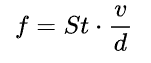
Where St is the Strouhal number (a dimensionless constant, approximately constant within a certain Reynolds number range).
2. Flow Calculation
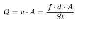
By measuring the vortex frequency f and combining it with the pipeline cross-sectional area A, the volumetric flow rate Q of the fluid can be calculated:
II. Structural Components
1. Bluff Body
- Shape: Common shapes include cylinder, triangular prism, rectangular prism, etc. The triangular prism is widely used because the vortices it generates are stable and the signal is strong.
- Function: Forces the fluid to generate vortices and optimizes vortex stability and frequency consistency through its shape.
2. Frequency Detection Element
- Type: Commonly used types include piezoelectric sensors, capacitive sensors, thermistors, etc.
- Function: Detects vibration or pressure changes generated by vortices and outputs electrical signals.
3. Signal Processing Unit
- Function: Amplifies, filters, and digitizes the electrical signals from the detection element, calculates the vortex frequency and flow value, and outputs them through a display panel or communication interface.
4. Pipeline and Connection Components
- Includes upstream and downstream straight pipe sections (to ensure stable fluid flow), flange or threaded connectors, etc.
III. Main Features
1. Advantages
- High measurement accuracy (generally ±1%~±1.5%) and good repeatability.
- Wide measurement range, with a turndown ratio of up to 10:1~20:1.
- No moving parts, low pressure loss, high reliability, and low maintenance.
- Can measure liquids, gases, and steam, with wide applicability.
2. Disadvantages
- Has certain requirements for the Reynolds number of the fluid; measurement error increases at low Reynolds numbers.
- Sensitive to flow velocity distribution in the pipeline; the lengths of upstream and downstream straight pipe sections must be strictly ensured (usually 10D upstream and 5D downstream, where D is the pipe inner diameter).
- Not suitable for fluids with low flow velocity, high viscosity, or large amounts of impurities (such as slurry).
- Vibration environments may interfere with measurement signals; vibration reduction measures are required.
IV. Applicable Scenarios
1. Industrial Process Measurement
Commonly used in industries such as petroleum, chemicals, metallurgy, and power to measure the flow of media such as water, oil, steam, and air. For example: steam flow monitoring in chemical pipelines and wastewater flow measurement in sewage treatment plants.
2. Trade Settlement and Energy-Saving Monitoring
Due to relatively high accuracy, it can be used for energy metering (such as trade settlement of steam flow) or equipment energy consumption analysis.
3. Clean Fluid Measurement
Suitable for clean, low-viscosity fluids; not suitable for media containing particles, fibers, or prone to crystallization.
V. Key Points for Selection and Installation
1. Key Parameters for Selection
- Medium type, temperature, pressure, and flow velocity range;
- Pipeline size and installation method (flange connection, clamp-on type, etc.);
- Output signal type (such as 4~20mA, pulse, RS485, etc.).
2. Installation Requirements
- Ensure the lengths of upstream and downstream straight pipe sections, avoiding interference from valves, elbows, reducers, etc., on flow velocity distribution;
- Install the sensor coaxially with the pipeline to avoid eccentricity;
- In vibration environments, vibration-damping brackets should be added; during gas measurement, avoid liquid accumulation in the pipeline.