
FMU30 Ultrasonic Level Measuring Instrument Installation and Wiring Precautions
The installation and wiring of the FMU30 ultrasonic level measuring instrument directly determine measurement accuracy and operational reliability. The manual emphasizes that incorrect installation may cause signal interference or measurement failure; incorrect wiring may cause equipment failure or safety risks. The following summarizes key points from both installation and wiring aspects.
I. Installation Precautions
Installation is the foundation for ensuring accurate measurement of the FMU30, involving position selection, environmental conditions, mechanical fixation, and post-installation verification. The following is explained in four subsections.
1. Installation Conditions and Environmental Requirements
- Position selection: Avoid installing the sensor in the center of the tank. The recommended distance between the sensor and the tank wall is 1/6 of the tank diameter to reduce interference. No devices such as limit switches or heating coils shall be within the signal beam angle (α).
For example, a 1½° sensor at a 5m range has a maximum beam radius of 0.48m; ensure no obstructions within this range.
- Special scenario handling:
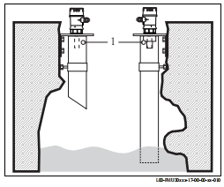
- Guided wave tube installation: In narrow or high-interference environments (such as wastewater pipes), use a guided wave tube (PE or PVC) with a minimum diameter of 100mm, and clean regularly to avoid dust accumulation.
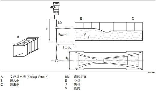
- Flow measurement: The instrument must be installed on the liquid inflow side, with the sensor diaphragm parallel to the water surface. For example, in a Venturi flume installation, the instrument should be located above the centerline.
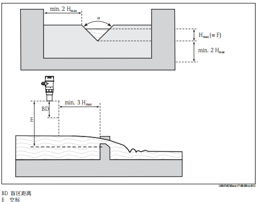
Triangular weir installation must meet specific distance requirements:
- Environmental factors: A protective cover must be installed to prevent sunlight and rain. The process temperature range is -20~60°C, and the process pressure is 0.7~3bar abs. Media with high vapor pressure (such as ethanol) may affect accuracy; consult the manufacturer.
2. Measurement Range and Blind Zone Handling
- Blind zone distance (BD): The highest material level must not enter the blind zone (e.g., for 2* sensor, BD is 0.35m), otherwise the signal cannot be recognized. When installing a short pipe, the inner wall must be smooth and burr-free, and the end must be chamfered at 45° to minimize interference.
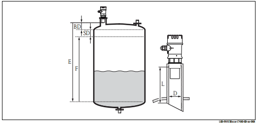
BD blind zone distance F full scale (full range) SD safety distance D installation short pipe diameter E empty calibration L installation short pipe length
- Safety distance (SD): Set the SD value in function parameter 015. When the level enters SD, the instrument triggers a warning or alarm to prevent overflow risk.
3. Installation Steps and Mechanical Fixation
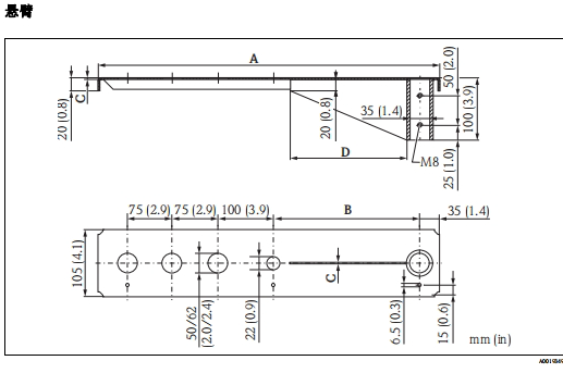
- Fixing method: Use mounting brackets, threaded flanges, or cantilevers. For example, cantilever with bracket installation:
When tightening bolts, only screw into the thread, use a 65AF wrench to apply a torque of max. 7 Nm:
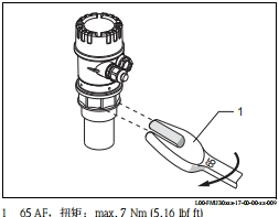
Be careful not to overtighten, which may damage the seal.
4. Post-Installation Check
After installation, perform visual and operating condition checks:
- The instrument is undamaged and meets process temperature/pressure requirements.
- Cable glands are tightened, and the housing seal is intact.
- Verify that the measurement range matches the actual operating conditions.
II. Wiring Precautions
Wiring involves electrical safety and signal stability. The manual warns that incorrect wiring may cause equipment failure or safety risks (Section 4.1). For explosion-proof applications, the "Safety Guide" (Section 1.3) must also be followed.
1. Wiring Steps and Safety Measures
- Preparation and warnings:
- Turn off the power and confirm that the supply voltage matches (14-35V DC) (Section 4.3).
- For hazardous area applications, use specified cable glands and comply with national standards (Section 4.1).
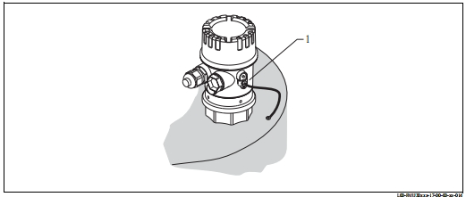
- The equipotential bonding terminal must be reliably grounded with a cross-sectional area of ≥2.5mm² (14AWG), and the length should be as short as possible to reduce EMC interference (Section 4.4):
- Wiring process (Section 4.1.1):
- Unscrew the housing cover and remove the display unit (optional).
- Insert the cable through the cable gland from the top (forming a drainage loop), and connect the shield to the ground terminal.
- Wire according to the terminal assignment diagram.
- Tighten the cable gland, reinstall the display unit and housing cover.
- Power on and test.
2. Terminal Assignment and Voltage Management
The terminals support cable cross-sectional areas of 0.25-2.5mm² (Section 10.1.3). The specific assignment is as follows:
| Terminal | Function |
|---|---|
| 1-2 | Power input (14-35V DC) |
| 3-4 | Current output (4-20mA) |
- Potential equalization: In explosion-proof applications, the sensor end must be grounded separately to avoid interference from multiple grounding points (Section 4.4).
3. Post-Connection Check
Verify after wiring is completed (Section 4.5):
- Terminal assignment is correct, and cable glands and housing cover are tightened.
- After power-on, check whether the display unit operates normally (Section 5.1). If there is an error code (such as A231 sensor fault), troubleshoot.