
FTL31 Liquid Tuning Fork Switch Installation and Wiring Guide
The FTL31 liquid tuning fork switch is widely used in industrial liquid level detection. Correct installation and wiring are key to ensuring its reliable operation. Based on official materials, this article systematically summarizes the key points of installation, wiring, and debugging for reference by engineering technicians and procurement personnel.
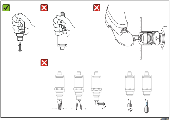
I. Installation Precautions
1. Safety Preparation
- Personnel Qualifications: Must be operated by trained and qualified professionals who are familiar with national regulations and wear protective equipment.
- Working Environment: Be sure to cut off the power supply before wiring, and avoid contact with surfaces with high temperatures above 80℃.
- Handling Specifications:
- Do not carry by holding the fork body; hold the housing or use the original packaging.
- Avoid bending, shortening the fork body, or using it as a climbing tool.
2. Installation Position and Orientation
The FTL31 supports installation at any position on a container or pipeline, but the installation orientation will affect the switch point offset (offset value A at water +25℃).
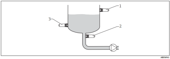
- Viscosity Adaptability:
- High-viscosity liquids: Do not use installation short pipes; ensure that the liquid can drain along the fork body.
- Low-viscosity liquids: The short pipe diameter must be ≥50mm (2.0in).
- Tank Wall Spacing: The distance between the fork body and the tank wall should be ≥10mm (0.39in) to prevent adhesion.
3. Pipeline and Tank Installation
- Pipeline Installation: Avoid medium turbulence; the fork body orientation must be parallel to the flow direction.
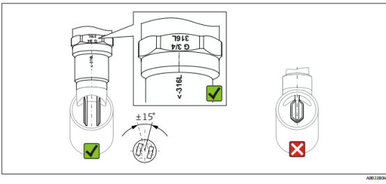
- Tank Horizontal Installation:
- The fork body marking should face upward.
- The cable connector (such as M12) should face downward to prevent water vapor from entering.
4. Fastening and Sealing
- Torque Control: Use an open-end wrench to tighten the hexagonal bolt; maximum torque ≤30 Nm (22 lbf ft).
- Sealing Material: NPT threads need to be wrapped with sealing material.
II. Wiring Precautions
1. Working Mode Selection
- High Limit Detection (MAX): The contact is normally closed when the fork body is not covered (overflow protection).
- Low Limit Detection (MIN): The contact is normally closed when the fork body is covered (pump dry-run protection).
- Fail-Safe: The contact is forced to open on alarm or power failure (quiescent current principle).
2. Three-Wire DC-PNP Wiring
Suitable for PLC digital input modules (EN 61131-2 standard).
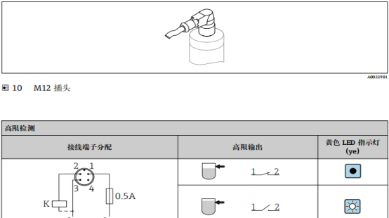
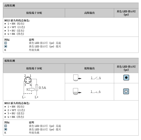
| Pin | Wire Color | Function |
|---|---|---|
| 1 | BK (Black) | Power + |
| 2 | GR (Gray) | Switching Output |
| 3 | BN (Brown) | Power - |
Grounding Requirement: Functional grounding must be connected.
3. Two-Wire AC/DC Wiring
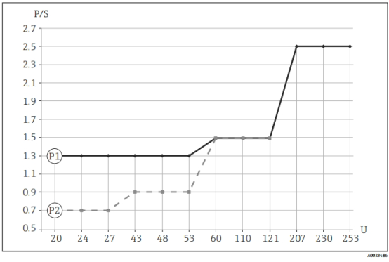
- Load Matching: The relay must meet the minimum power:
- 24V DC: 0.7–6W
- Overload Protection: Automatically cuts off when current >250mA, and recovers after fault repair.
- Polarity Protection: Built-in reverse connection protection; incorrect wiring automatically shuts down.
4. General Wiring Specifications
- Cable Gland Tightening: Eliminate cable stress and ensure sealing.
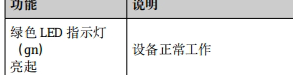
- Power-On Check: The green LED lights up to indicate normal power supply.
III. Debugging and Verification
1. Functional Test
- Magnet Test:
- Place the test magnet at the housing marking for ≥2 seconds; the yellow LED status switches.
- Warning: Placing the magnet for >30 seconds triggers the protection function (red LED flashes).
2. LED Diagnosis
| LED Status | Fault Cause | Measure |
|---|---|---|
| Red steady on | Internal sensor fault | Replace device (§8.1) |
| Red flashing | Load short circuit/overcurrent | Check circuit, current |