
I. Overview of CM442 Dissolved Oxygen Measurement Applications and Configuration
The core applications of dissolved oxygen (DO) in industry revolve around "ensuring production safety, improving product quality, optimizing process efficiency, and reducing equipment wear." Different industries monitor or regulate dissolved oxygen content to solve key issues such as corrosion, reaction efficiency, and product degradation in processes.
This article uses the CM442 transmitter paired with the COS51E membrane-covered dissolved oxygen sensor as an example to introduce the complete process from wiring, startup, parameter setting to calibration, making it easy for engineering technicians and procurement personnel to get started quickly.
II. CM442 Wiring and Startup
2.1 Power Supply and Measurement Cable Wiring
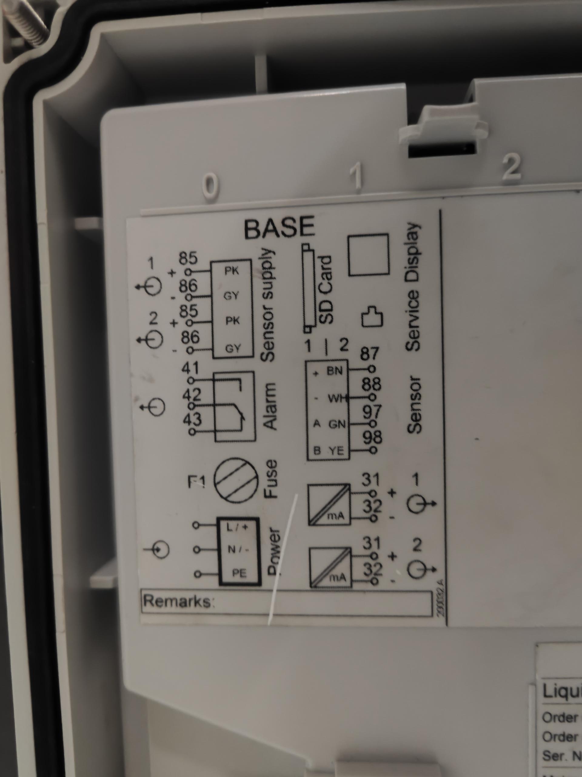
- Connect a 24V DC power supply to the L and N terminals, noting that N is the positive pole and L is the negative pole.
- Connect the measurement cable to terminals 87, 88, 97, and 98 in the order of brown, white, green, and yellow.
- Connect the measurement cable to the COS51E sensor, confirm the connection is secure, and then turn on the power.
| Wiring Position | Connection Object | Wiring Description |
|---|---|---|
| L / N terminals | 24V power supply | N is positive, L is negative |
| 87 / 88 / 97 / 98 | Measurement cable | Connect in the order of brown, white, green, yellow |
2.2 Startup Status Confirmation
After power-on, the instrument self-checks and enters the measurement interface, at which point measurement settings can be performed. If the display is abnormal, first check whether the power supply polarity and the measurement cable connection order are correct.
III. Keypad and Jog Dial Operation Instructions
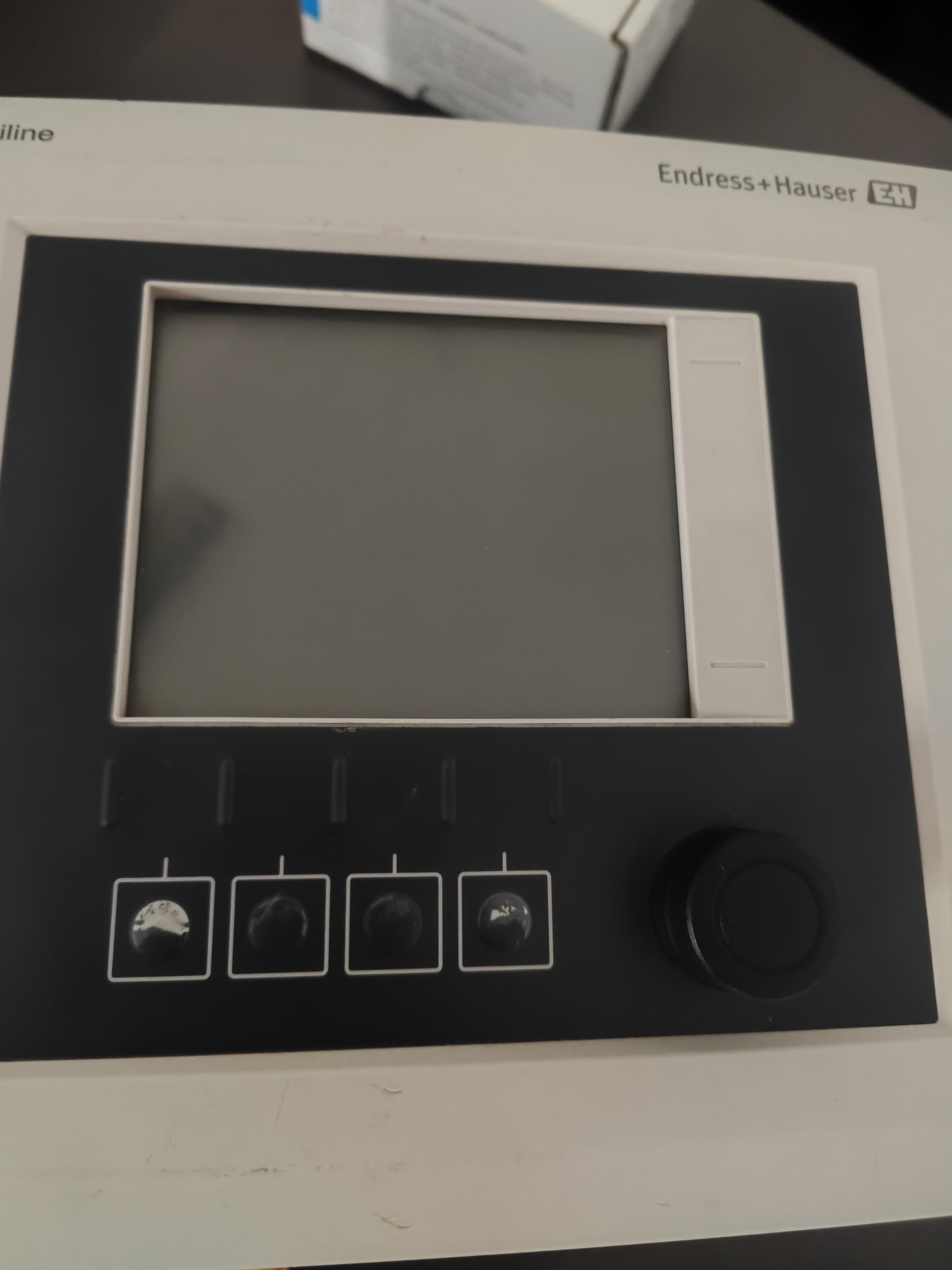
After the instrument starts successfully, menu operations can be performed. The key functions on the main interface and the jog dial operation are as follows:
- First key: Enter the main menu bar.
- Second key: Calibration menu.
- Third key: Diagnostics menu.
- Fourth key: Help menu.
- Jog dial: Rotate clockwise to move down, rotate counterclockwise to move up, press to confirm.
IV. Basic Parameter Settings: Setup → Input → Channel 1
After entering the instrument menu bar, select the Setup option in sequence, and within the setup interface further select the Input function module. Under the input module, select Channel 1 as the configuration object, enter the parameter setting interface for Channel 1, and complete the settings in the following order:
- Set the sensor type to membrane-covered method to match the COS51E sensor.
- For the primary value parameter, usually select liquid concentration as the default measurement type.
- Regarding the damping parameters (two items in total), the default settings can satisfy most conventional operating conditions; if there are special measurement accuracy or response speed requirements, adjust according to the actual scenario.
- Modify the measurement unit in the corresponding parameter item according to usage habits or industry standards.
| Parameter Item | Recommended Setting | Description |
|---|---|---|
| Sensor type | Membrane-covered method | Must be consistent with COS51E |
| Primary value | Liquid concentration (default) | Can switch to saturation in special scenarios |
| Damping (two items) | Default values | Adjust according to accuracy and response speed requirements |
| Measurement unit | According to industry standards | Such as mg/L, %, etc. |
V. Extended Settings: Matching the Instrument to On-Site Conditions
The core goal of extended settings is to precisely match the instrument with actual on-site conditions (such as medium characteristics and environmental conditions) and eliminate interference from external factors on measurement results. After entering the extended settings interface, the following key parameters can be adjusted one by one, and all settings should be based on the principle of complying with industry measurement standards and ensuring data stability.
5.1 Temperature Compensation
Temperature is the core factor affecting the solubility of dissolved oxygen, and the compensation mode must be selected according to whether there are temperature fluctuations in the measurement environment.
- Manual temperature compensation: Select when the on-site temperature is stable (such as in constant-temperature water bodies), and input the current actual ambient temperature value, accurate to 0.1°C.
- Automatic temperature compensation: Enable when the on-site temperature fluctuates frequently (such as outdoor water bodies and industrial wastewater). The instrument uses a built-in temperature sensor to correct the dissolved oxygen measurement value in real time, avoiding temperature drift errors. The compensation range is recommended to be set to -10°C~60°C, which can cover most industrial scenarios.
5.2 Primary Value Format
The primary value format determines the form of the core measurement data displayed by the instrument and must be selected in combination with industry habits and monitoring needs.
- Liquid concentration (mg/L): A common choice for scenarios such as industrial wastewater and aquaculture, intuitively reflecting the actual content of dissolved oxygen in the water body.
- Saturation (%): In environmental monitoring and scientific research scenarios, if it is necessary to compare the degree of dissolved oxygen saturation at different temperatures, this format can be selected to facilitate judgment of the water body's oxygen supply capacity.
It is recommended to select liquid concentration by default; if switching is needed, it can be adjusted in the "Display Settings" submenu.
5.3 Temperature Format
The temperature format must be consistent with the temperature unit standard used on site. Domestic industrial scenarios default to Celsius (°C); scenarios for export equipment or adapting to North American and European standards can choose Fahrenheit (°F). After setting, confirm that the display is correct in the preview interface to avoid operational errors caused by unit confusion.
5.4 Medium Pressure
The solubility of dissolved oxygen is positively correlated with ambient pressure and must be corrected according to on-site pressure conditions.
- High-pressure water bodies (such as boiler feedwater and high-pressure reactors): Manually input the actual medium pressure value; the unit can be kPa or MPa. The input should refer to the on-site pressure gauge reading, with an error controlled within ±1kPa.
- Normal-pressure scenarios (such as open pools and natural water bodies): The default normal pressure of 101.3kPa can be selected, with no additional setting required.
5.5 Medium Selection and Subsequent Confirmation
After completing the medium type selection in the extended settings, the instrument will automatically load the basic parameters corresponding to that medium, reducing the amount of manual adjustment. The following two points should be confirmed subsequently:
- If the medium contains corrosive components (such as acid-base wastewater and chlorinated water bodies), check whether the sensor protection mode is automatically enabled to prevent the medium from damaging the sensor and affecting accuracy.
- If the medium has high viscosity and high suspended solids (such as slurry water and fermentation broth), select high turbidity adaptation in the measurement mode to extend the response time from the default 5 seconds to 10-15 seconds, ensuring stable measurement values.
VI. Output Settings: 4-20mA Data Transmission Configuration
Output settings are used to configure the parameters for the instrument to transmit data to the central control system (such as DCS, PLC), and it is necessary to ensure accurate data source, matching range, and stable signal.
6.1 Current Output Channel and Data Source Configuration
- Current output channel selection: If the instrument supports multi-channel output (such as Channel 1 and Channel 2), select the target current output channel according to the signal receiving port of the central control system to avoid data misrouting caused by channel confusion; single-channel instruments can directly default to "Channel 1."
- Data source specification: In the data source selection menu, it must be explicitly specified as membrane-covered method, consistent with the sensor type, to ensure that the output data is the true measurement value of the membrane-covered sensor and avoid data deviation caused by mistakenly selecting other data sources (such as backup sensors or analog signals).
6.2 Measurement Value Range (Upper and Lower Limits) Setting
The range must be set in combination with the actual on-site measurement range and the signal receiving range of the central control system (such as 4-20mA corresponding to 0-20mg/L), according to the principle of covering the actual maximum measurement value and reserving 10%-20% redundancy.
| Application Scenario | Recommended Lower Limit | Recommended Upper Limit |
|---|---|---|
| Sewage treatment, aquaculture | 0 mg/L | 20 mg/L |
| Boiler feedwater (requires DO<0.05mg/L) | 0 mg/L | Set according to actual needs |
| Industrial aeration tank (high-pressure oxygen-enriched) | 0 mg/L | Set according to actual maximum DO, such as 30 mg/L |
If the lower limit is too low or too high, it will affect the normal transmission of low-concentration data; if the upper limit is too low, high-concentration values will exceed the range and cannot be output normally.
VII. Calibration: Temperature Single-Point Calibration
After the above parameters are set according to actual needs, calibration can begin. Taking temperature calibration as an example, selecting single-point calibration is sufficient. After calibration is completed, it is recommended to review whether the measurement value is consistent with the value displayed by the central control system to confirm that the entire measurement chain is working properly.