
PMP43 Digital Pressure Transmitter Overview
The PMP43 is a compact digital pressure transmitter that uses a metal diaphragm sensor for process pressure measurement. Its working principle is that external pressure causes deformation of the metal diaphragm, and the fill fluid transmits the pressure to a Wheatstone resistance bridge (semiconductor technology). By measuring the change in bridge output voltage and calculating and processing it, the pressure value is obtained.
The measurement system includes a PLC and the device. Communication and data processing use a 4…20 mA superimposed HART digital signal, two-wire system, with optional Bluetooth.
Output Signal Types
The output signals of the PMP43 are divided into the following two categories. The specific parameters and mode descriptions are as follows:
- 4…20 mA superimposed HART digital signal (two-wire): Supports three different current output modes, which can be flexibly configured according to actual needs.
- 4…20.5 mA signal (compliant with NAMUR NE 43 standard): Includes two specifications, namely the factory default setting of 3.8…20.5 mA, and the US standard specification of 3.9…20.5 mA.
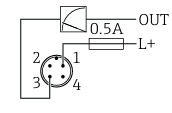
Its electrical connection method is shown in the figure:
Electrical Connection and Power Supply
The supply voltage is 12-30 V DC (DC power supply unit). The requirements for 4…20 mA communication are the same as for HART communication. Explosion-proof devices must use an electrically isolated active safety barrier.
The device is equipped with polarity reversal protection, high-frequency interference suppression, and overvoltage protection circuits. When used in non-explosion-proof hazardous areas, relevant safety regulations and protection standards must be strictly followed:
- The device operating current must not exceed 500 mA, and the instrument safety requirements specified in IEC 61010 must be met.
- The built-in overvoltage protection unit must comply with the IEC 61326-1 product standard, and the corresponding test voltage must be applied according to the connection type, with surge immunity testing performed (according to IEC 61000-4-5 Surge standard), where the line-to-ground test voltage for DC power lines and input/output lines is 1000 V.
- The overvoltage protection level is suitable for systems with overvoltage protection category II, complies with IEC 61010-1 standard, and can effectively withstand transient overvoltages commonly found in power distribution systems.
The connection of the terminals must be wired according to the following figure:
Operating Interface and Basic Operations
The following describes how to operate. The schematic diagram of the operating interface is as follows:
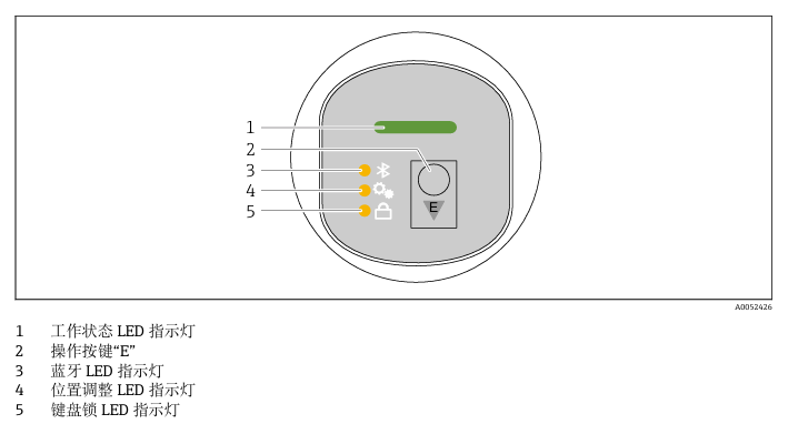
Select the corresponding indicator light according to requirements. Briefly press (2 s) the E operating key to operate the device:
- Briefly press the E operating key: Switch between various function parameters.
- Press and hold the E operating key: Select a function parameter. If a function parameter has been selected, the LED indicator flashes. Different flashing states indicate whether the function parameter is active or inactive.
Steps to Disable the Keypad Lock
- Press and hold the E operating key; the Bluetooth LED indicator flashes.
- Repeatedly briefly press the E operating key until the keypad lock LED indicator flashes.
- Press and hold the E operating key; the keypad lock function is disabled.
Enable or Disable Bluetooth Connection
- If necessary, disable the keypad lock function.
- Repeatedly briefly press the E operating key until the Bluetooth LED indicator flashes.
- Press and hold the E operating key. The Bluetooth connection is enabled (Bluetooth LED indicator lights up), or the Bluetooth connection is disabled (Bluetooth LED indicator goes out).
On-site Display Unit Functions
The operating menu can be accessed through the on-site display unit to implement multiple function operations:
- Display measured values, fault information, and prompt messages; when an error occurs, an icon is displayed simultaneously.
- Electronically adjustable design, supporting automatic or manual adjustment of the measured value display (rotated 90° each time), and the measured value display automatically rotates according to the orientation when the device is started.
- Basic settings can be made through the on-site display unit with touch functionality, including lock on/off, selection of display language, and Bluetooth on/off.
- Basic settings can be completed with the help of the commissioning wizard. Device information can also be read (such as name, serial number, firmware version number), current diagnostics and status information can be viewed, and device reset can be performed.
- Under bright light conditions, the display color can automatically invert, and the backlight display automatically adjusts according to the terminal voltage.
This concludes the introduction to basic operations.