
E+H pH Meter Wiring Diagram Overview
E+H (Endress+Hauser) pH meters and dissolved oxygen transmitters are widely used in industrial water treatment, chemical, pharmaceutical, and other industries. Whether the on-site wiring is correct directly affects measurement accuracy and instrument lifespan. This article organizes common wiring diagrams by model combination for reference by engineering and technical personnel and procurement.
All wiring diagrams are presented in the matching form of transmitter + electrode/cable. For actual wiring, please refer to the accompanying manual and on-site nameplate.
E+H pH Meter Wiring Diagrams (CPM223/CPM253 Series)
CPM223-MR0005 + CYK10 Wiring Diagram
This combination is a typical wiring method of a CPM223 transmitter with a CYK10 dedicated cable, suitable for conventional pH measurement applications.
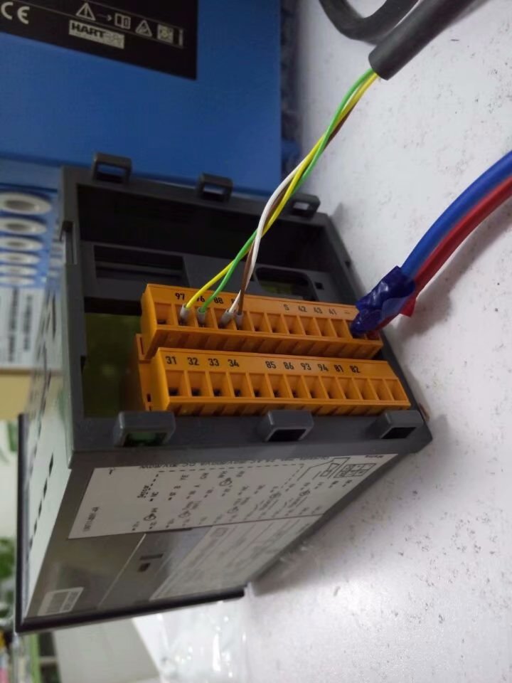
CPM253-MR0005 + CYK10 Wiring Diagram
CPM253 is a transmitter with a field display. When paired with the CYK10 cable, the terminal definitions are basically the same as those of the CPM223, but attention must be paid to distinguishing the power supply and output circuits.
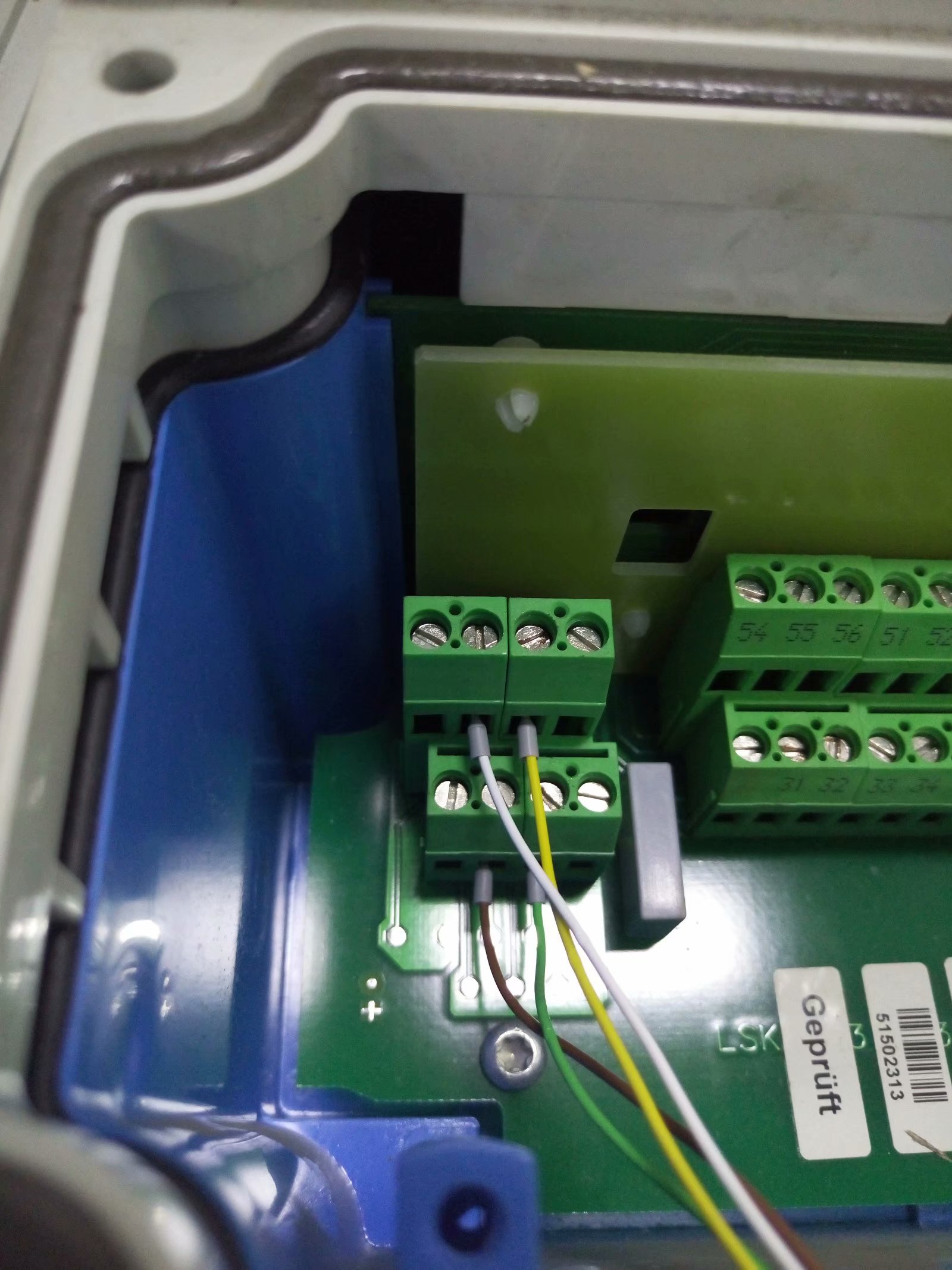
CPM223-PR0005 + CPK9 Wiring Diagram
This combination uses a CPK9 cable, suitable for specific electrode interfaces or explosion-proof applications. During wiring, the connection method of the cable shield and the grounding terminal must be confirmed.
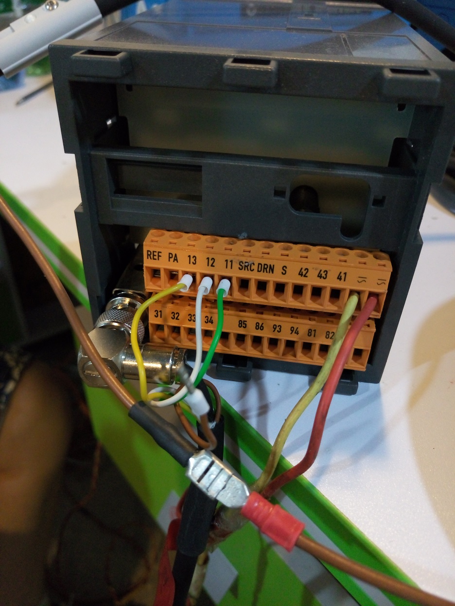
CPM253 + CPF81 Wiring Diagram
CPF81 is a pH electrode. When connected to the CPM253 transmitter, the measuring wire, reference wire, and shield wire must be connected according to the color or terminal number.
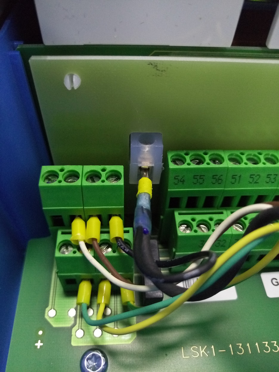
E+H Dissolved Oxygen Wiring Diagrams (COM223/COM253 Series)
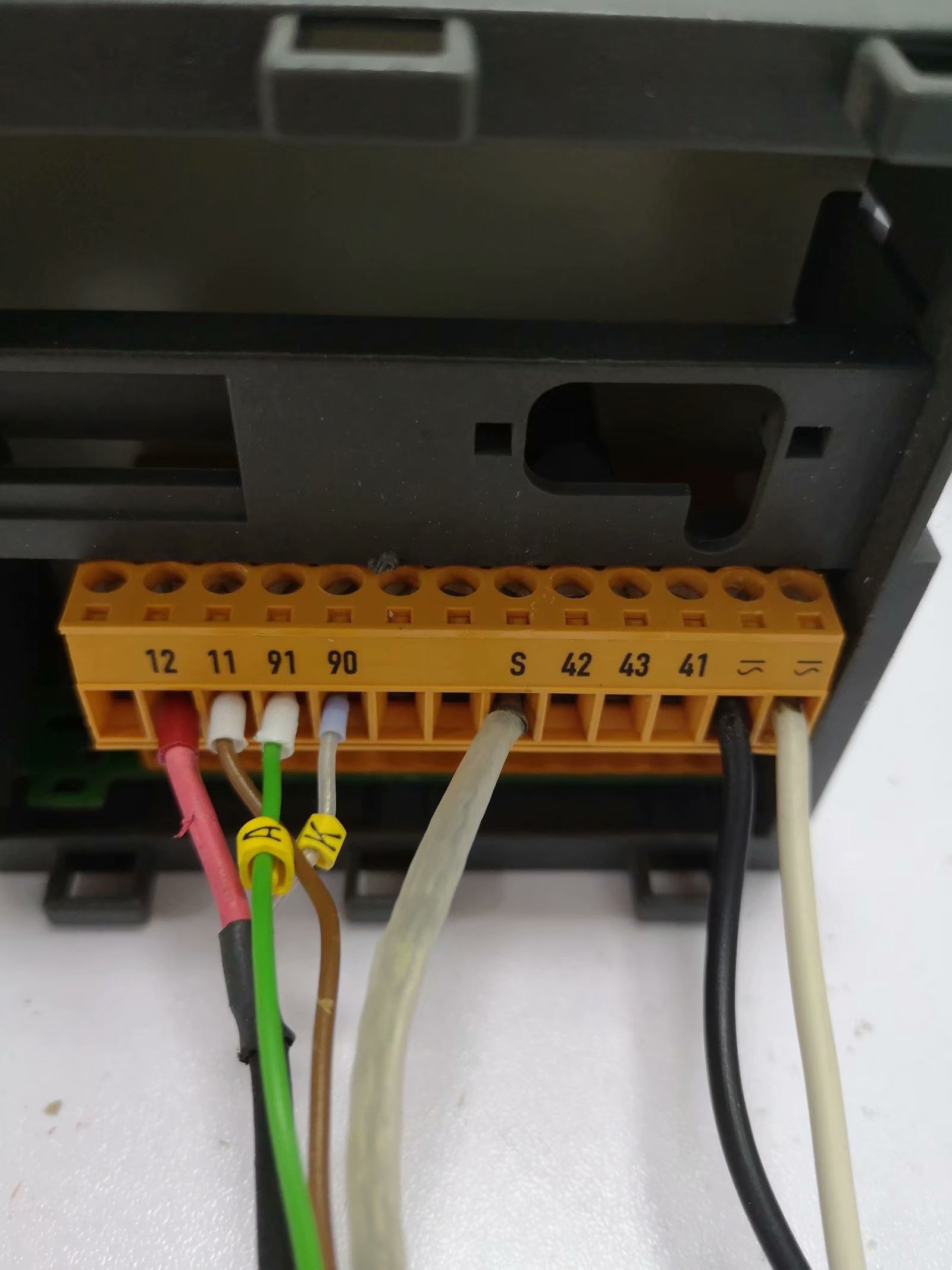
COM223 + COS41 Wiring Diagram
The COM223 dissolved oxygen transmitter is paired with a COS41 dissolved oxygen electrode, commonly used in applications such as sewage treatment aeration tanks. During wiring, pay attention to the electrode polarity and the corresponding relationship of the temperature compensation wires.
COM253 + COS41 Wiring Diagram
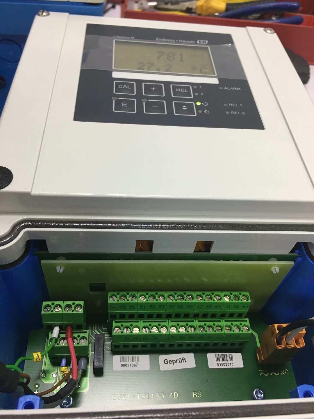
COM253 is a field display dissolved oxygen transmitter. Its wiring method with the COS41 electrode is similar to that of the COM223, but the terminal layout may differ slightly.
Common Models and Matching Cable/Electrode Comparison Table
| Transmitter Model | Matching Cable/Electrode | Typical Application |
|---|---|---|
| CPM223-MR0005 | CYK10 | pH measurement |
| CPM253-MR0005 | CYK10 | pH measurement (with display) |
| CPM223-PR0005 | CPK9 | pH measurement (specific interface) |
| CPM253 | CPF81 | pH measurement |
| COM223 | COS41 | Dissolved oxygen measurement |
| COM253 | COS41 | Dissolved oxygen measurement (with display) |
Wiring Precautions
- Before wiring, be sure to disconnect power and confirm that the transmitter supply voltage matches the nameplate.
- The cable shield should be grounded at one end to avoid ground loop interference.
- The pH measuring wire, reference wire, and temperature compensation wire must be connected to the corresponding terminals and must not be mixed.
- The polarity and temperature compensation wiring of the dissolved oxygen electrode must be strictly implemented according to the diagram.
- After wiring is completed, it is recommended to use a multimeter to check insulation and continuity before powering on for commissioning.
Summary
This article summarizes common wiring diagrams for E+H pH meters and dissolved oxygen transmitters, covering the matching wiring of models such as CPM223, CPM253, COM223, and COM253 with CYK10, CPK9, CPF81, and COS41. For actual construction, please refer to the official manual to ensure correct wiring and reliable grounding.