
TMT71 Temperature Transmitter Wiring Overview
TMT71 is a modular temperature transmitter that supports multiple sensor input types, including thermocouples and RTDs. Correct wiring is key to ensuring measurement accuracy and system stability. This article will detail the terminal connections for different sensors.
Sensor Wiring Methods
Thermocouple Wiring
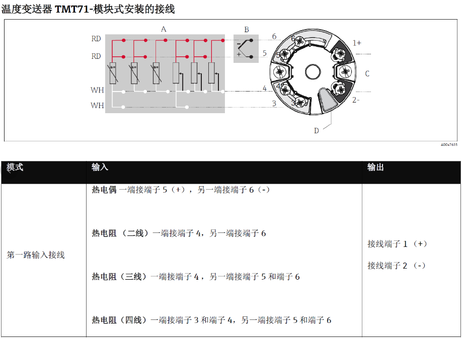
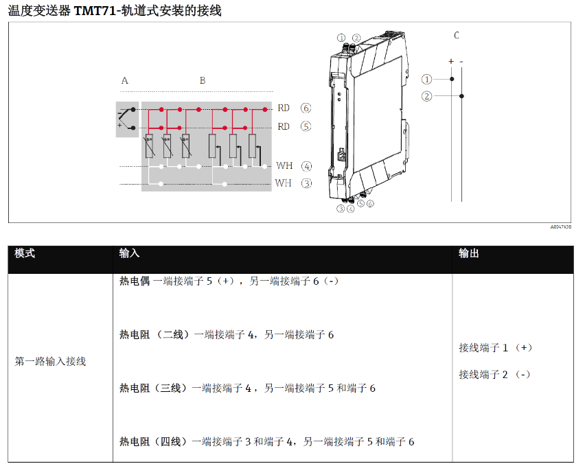
The thermocouple signal is connected to terminals 5 (+) and 6 (-). Pay attention to polarity; reverse connection will cause the measured value to be reversed or incorrect.
RTD Wiring
RTD wiring varies depending on the wire configuration, as follows:
- Two-wire: one end connects to terminal 4, the other end connects to terminal 6.
- Three-wire: one end connects to terminal 4, the other end connects to terminals 5 and 6.
- Four-wire: one end connects to terminals 3 and 4, the other end connects to terminals 5 and 6.
Terminal Quick Reference Table
| Sensor Type | Terminal Connection |
|---|---|
| Thermocouple | 5(+), 6(-) |
| RTD (two-wire) | 4, 6 |
| RTD (three-wire) | 4, 5 and 6 |
| RTD (four-wire) | 3 and 4, 5 and 6 |
Wiring Diagrams
Below are the wiring diagrams for the TMT71 temperature transmitter for reference during actual wiring.
Precautions
- Before wiring, confirm that the power supply is disconnected to ensure operational safety.
- Use shielded cables and ensure proper grounding to reduce electromagnetic interference.
- Ensure terminal screws are tightened to avoid poor contact.
- For three-wire and four-wire RTDs, use wires of the same length and specification as much as possible to minimize line resistance errors.