CM44x Transmitter Dissolved Oxygen Commissioning Guide
The CM44x transmitter, when used with dissolved oxygen sensors, can accurately measure the dissolved oxygen concentration in water. This article provides complete commissioning steps, including installation, wiring, key functions, settings, calibration, fault codes, and maintenance, to help you get started quickly.
1. Installation
The CM44x transmitter supports three installation methods, which can be selected according to site conditions.
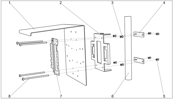
1.1 Vertical Pipe Installation
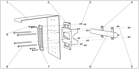
1.2 Horizontal Pipe Installation
1.3 Wall Mounting
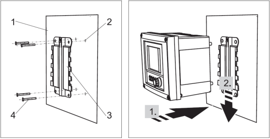
Note: Vertical and horizontal pipe installations require additional installation accessories to be ordered.
2. Wiring
Before wiring, please confirm the supply voltage on the transmitter nameplate to ensure correct connection.
2.1 Power Wiring
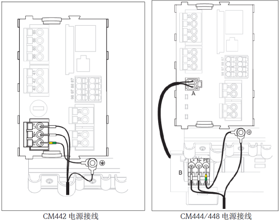
Note: Please check whether the CM44x nameplate indicates 220VAC or 24VDC power supply.
2.2 Dissolved Oxygen Sensor Wiring
Wiring methods vary slightly for different sensor models. Please select the corresponding wiring method according to the sensor model.
2.2.1 COS51D/COS21D/COS22D Sensor Wiring
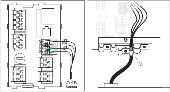
- Connect the four cable wires (brown, white, green, yellow) to terminals 87, 88, 97, and 98 respectively.
- The sensor cable shield must be grounded.
- Connect the current output to terminals 31 and 32. The current output is an active output.
Note: Ensure all cable glands are tightened and sealed.
2.2.2 COS61D Sensor Wiring
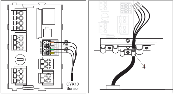
- Connect pink, gray, green, and yellow to terminals 85, 86, 97, and 98 respectively.
- The sensor cable shield must be grounded.
- Connect the current output to terminals 31 and 32. The current output is an active output.
Note: Ensure all cable glands are tightened and sealed.
3. Key Functions
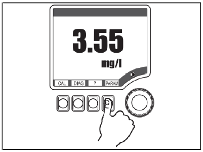
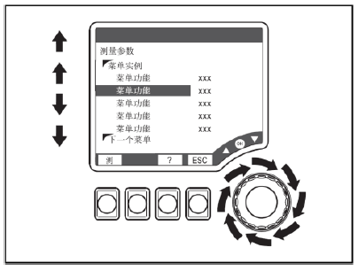
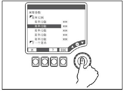
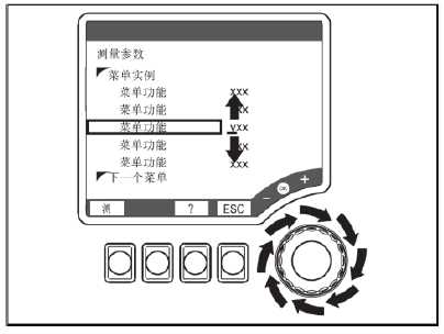
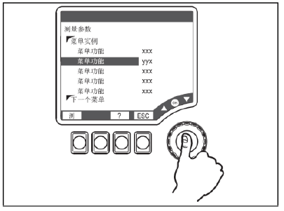
The CM44x transmitter uses a combination of soft keys and a navigator. Familiarity with key functions can improve commissioning efficiency.
- Press soft key: directly select the menu.
- Rotate navigator: move the cursor within the menu.
- Press navigator: select the function.
- Rotate navigator: change the value.
- Press navigator key: accept the new value.
4. Settings
Correct parameter settings are a prerequisite for ensuring measurement accuracy.
4.1 Range Setting
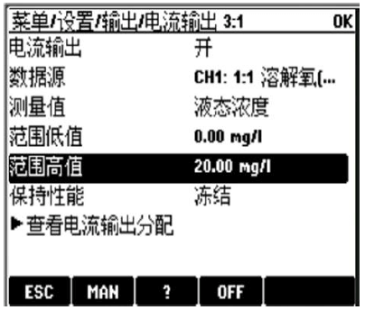
Set the "Range Low" and "Range High" in the "Menu/Setup/Output/Current Output x:x" menu.
4.2 Transmitter Reset
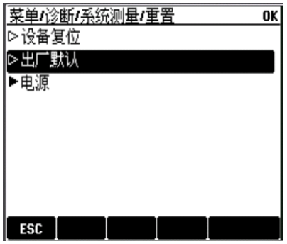
Select "Factory Default" in the "Menu/Diagnostics/System Measurement/Set" menu to reset the transmitter.
5. Calibration
Calibration is a key step to ensure accurate measurement, including slope calibration and zero point calibration.
5.1 Slope Calibration
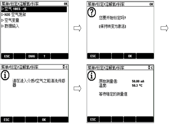
Enter "Menu/Calibration/Dissolved Oxygen" and select "Air 100%rH". Follow the on-screen prompts to complete the slope calibration. After calibration, the status is displayed, asking whether to adjust the calibration data. If calibration fails, an error message is displayed.
5.2 Zero Point Calibration
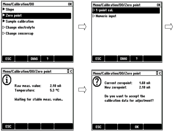
When measuring trace dissolved oxygen (ppb level) in ultrapure water, zero point calibration must be performed using a zero solution.
- Add half a bottle of zero point powder to 1 liter of tap water and dissolve thoroughly, then place the fully polarized sensor into the zero solution.
- Press the CAL key and follow the path below for calibration.
Remarks:
- Pay attention to the sensor polarization time; some sensors require 12 hours for complete polarization.
- During zero point calibration, the signal is generally below 1 nA. If it exceeds 3 nA, an alarm is triggered, indicating zero point calibration failure!
6. Common Fault Codes
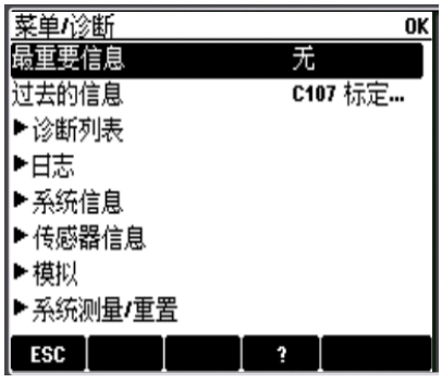
Fault codes and their meanings are automatically displayed on the measurement interface; you can enter "Menu/Diagnostics" to view fault codes and press the "?" key to view the fault meaning.
7. Sensor Maintenance
Regular maintenance can extend sensor life and ensure measurement accuracy.
7.1 Maintaining COS31/41/51D/71
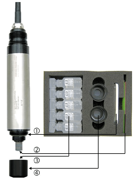
- Replace the sealing ring if damaged.
- Drop a few drops of water on the sandpaper and polish the gold cathode at the front of the sensor for 1 minute.
- Refill with fresh electrolyte. Tap the membrane cap with a screwdriver to remove attached air bubbles.
- Screw the new membrane cap all the way down to prevent membrane rupture.
- Recalibrate the sensor in air, avoiding direct sunlight.
7.2 Maintaining COS61(D)
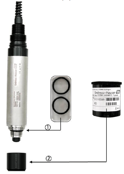
- Replace the sealing ring if damaged.
- Screw the new membrane cap all the way down, avoiding sunlight.
- Recalibrate the sensor in air, avoiding direct sunlight.
Note: If measurement is inaccurate, perform zero point calibration on the sensor. Before zero point calibration, place the sensor in zero solution for 2-3 hours. Prepare zero solution by adding half a bottle of zero point powder to 1 liter of water; its validity period is 1 day.
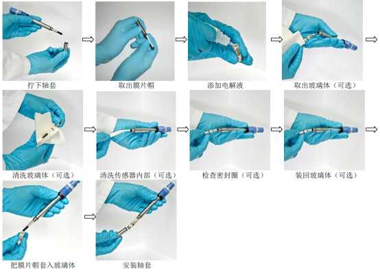
7.3 Maintaining COS22(D)
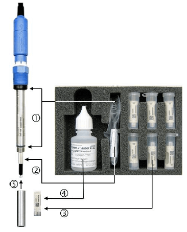
- Replace the sealing ring if damaged.
- Replace the glass body (optional, if the cathode is contaminated).
- Replace the membrane cap (optional, if the membrane is damaged).
- Refill with fresh electrolyte, use a screwdriver to tap the membrane cap to remove attached air bubbles.
- Screw the sleeve all the way down, recalibrate the sensor in air, avoiding direct sunlight.
Note: If measurement is inaccurate, perform zero point calibration on the sensor. Before zero point calibration, place the sensor in zero solution for 2-3 hours. Prepare zero solution by adding half a bottle of zero point powder to 1 liter of water; its validity period is 1 day.
The specific maintenance steps are illustrated as follows: