
COM253/223 Dissolved Oxygen Transmitter Installation and Commissioning Guide
The COM253/223 transmitter, together with dissolved oxygen sensors, is widely used for dissolved oxygen measurement in fields such as water treatment and environmental monitoring. This article systematically introduces its installation, wiring, keypad operation, parameter setting, calibration and maintenance methods.
1. Installation Methods
The COM253 transmitter supports three installation methods, which can be selected according to the site environment.
1.1 Wall Mounting
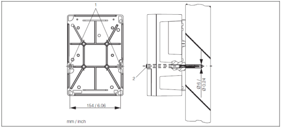
Use the two Ø6 holes at position 1 on the back of the transmitter to fix it to the wall with screws. At the factory, these two holes are plugged with black plugs (position 2), which need to be removed during installation.
1.2 Pipe Mounting
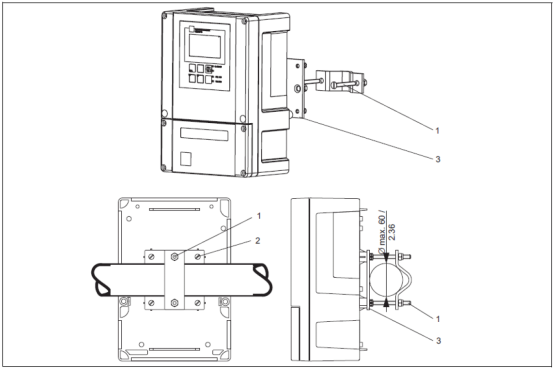
Vertical or horizontal pipe mounting can be used. During installation, use the four M5 screw holes on the back of the transmitter (position 2). The maximum pipe diameter is Ø60.
1.3 Weather Protection Mounting
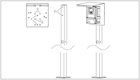
Weather protection mounting requires additional ordering of installation accessories, and the weather protection cover must be ordered separately as an accessory. If the transmitter is installed outdoors in an open-air environment, it is recommended to use a weather protection cover to protect the instrument.
2. Wiring Methods
The wiring method varies depending on the transmitter model and the matched sensor.
2.1 COM253-X/DS Transmitter (with COS41 Sensor)
During measurement, please refer to the following figures for wiring:

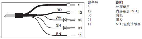
- Terminals marked "NC" and unmarked terminals are not connected.
- Connect the 220VAC power supply to terminals L1 and N; connect the 24VDC power supply to terminals + and -.
- Connect the first current output (dissolved oxygen) to terminals 31 and 32, and the second current output (temperature, optional) to terminals 33 and 34. The current output is an active output.
2.2 COM253-WX/WS Transmitter (with COS31, COS61 or COS71 Sensor)
During measurement, refer to the following figure for wiring:
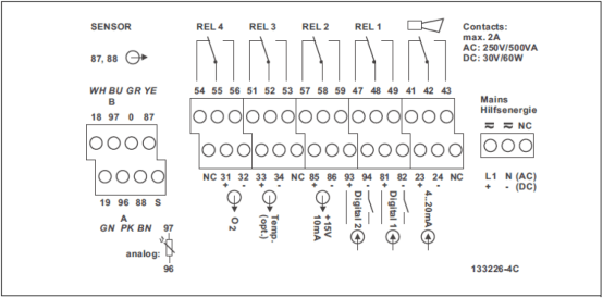
- The COS31, COS61 and COS71 sensors come with cables and are directly connected to the transmitter through the SXB seven-pin plug.
- Terminals marked "NC" and unmarked terminals are not connected.
- Connect the 220VAC power supply to terminals L1 and N; connect the 24VDC power supply to terminals + and -.
- Connect the first current output (dissolved oxygen) to terminals 31 and 32, and the second current output (temperature, optional) to terminals 33 and 34. The current output is an active output.
Note: Ensure that all cable glands are tightened and sealed.
3. Keypad Functions
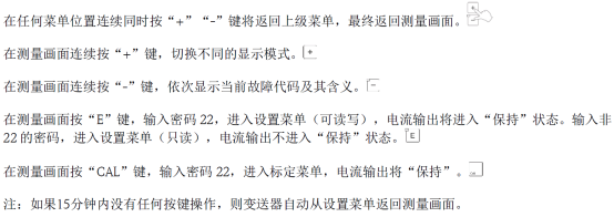
3.1 Description of Basic Keypad Functions
3.2 Keypad Locking and Unlocking

4. Parameter Setting
4.1 Sensor Setting
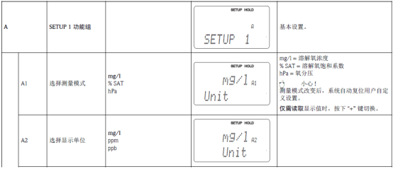
Press the "E" key and enter password "22". Under the "SETUP1" menu, select the measurement mode and display unit in the "A1, A2" menus. If pressure, altitude or salinity compensation is required, set it in other submenus in SETUP1 and SETUP2.
4.2 Range Setting
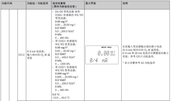
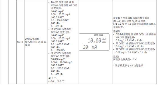
Under the "Current Output" menu, set the range corresponding to 4-20mA. In 01, select the current output channel. When the instrument has dual-channel output, OUT1 and OUT2 can be selected; when it has single-channel output, directly proceed to the next item. OUT1 is used as the current output for dissolved oxygen; OUT2 is used as the current output for temperature.
4.3 Transmitter Reset
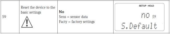
Under the "Service" menu, in the "S9" menu, select "Facty" to reset the transmitter.
5. Calibration
Press the "CAL" key and enter password "22". Complete the slope calibration under the "Calibration" menu.
- In the "C1" menu, select "Air" calibration in air and press the "CAL" key.
- Take the sensor out of the medium and wipe it clean.
- After the measured value stabilizes in air, the system automatically enters the "C111" menu and starts calibration, entering the countdown. The calibration time is at most 600s.
- Enter the "C112" menu, which displays whether calibration passed or an error occurred.
- In the "C113" menu, select whether to save the calibration data, discard it, or recalibrate.
When measuring trace dissolved oxygen (ppb level) in ultrapure water, zero-point calibration must be performed using a zero-point calibration solution:
- Add half a bottle of zero-point powder to 1 liter of tap water and dissolve it thoroughly, then place the fully polarized sensor into the zero-point calibration solution.
- Press the CAL key and select zero-point calibration.
Remarks: Pay attention to the polarization time of the sensor; some sensors require 12 hours to be fully polarized. During zero-point calibration, the signal is generally below 1nA. If it exceeds 3nA, an alarm will be triggered, indicating that zero-point calibration has failed!
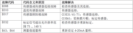
6. Common Fault Codes
7. Sensor Maintenance
7.1 Maintaining COS31/41/51D/71
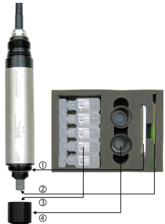
- Replace the sealing ring if it is damaged.
- Drop a few drops of water onto the sandpaper and polish the gold cathode at the front end of the sensor for 1 minute.
- Refill with fresh electrolyte. Tap the membrane cap with a screwdriver to remove attached air bubbles.
- Screw the new membrane cap all the way down to prevent the membrane from rupturing.
- Place the sensor in air for recalibration, avoiding direct sunlight.
7.2 Maintaining COS61(D)
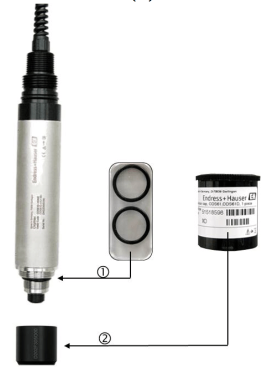
- Replace the sealing ring if it is damaged.
- Screw the new membrane cap all the way down to prevent sunlight exposure. Place the sensor in air for recalibration, avoiding direct sunlight.
Note: If the measurement is inaccurate, perform zero-point calibration on the sensor. Before zero-point calibration, place the sensor in the zero-point calibration solution for 2-3 hours. Add half a bottle of zero-point powder to 1 liter of water to prepare the zero-point calibration solution, which is valid for 1 day.