
CM42 Transmitter pH/ORP Basic Commissioning Guide
The CM42 transmitter is a core device for industrial pH/ORP measurement. Correct installation, wiring, and commissioning are crucial for measurement accuracy. This article is aimed at engineering technicians and procurement personnel and systematically introduces its commissioning process.
1. Installation Methods
The CM42 transmitter supports four installation methods to meet different on-site requirements.
1.1 Horizontal Pipe Installation
Suitable for horizontal pipes; additional installation accessories must be ordered.
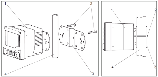
1.2 Vertical Pipe Installation
Suitable for vertical pipes; additional installation accessories must also be ordered.
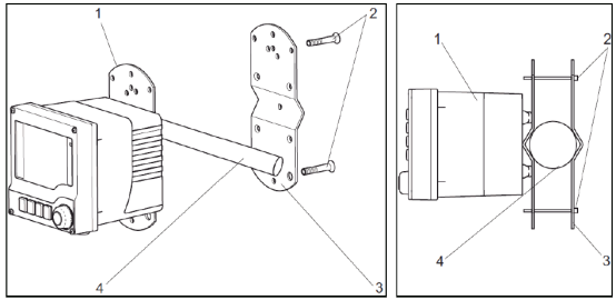
Note: Both horizontal and vertical pipe installations require additional installation accessories to be ordered.
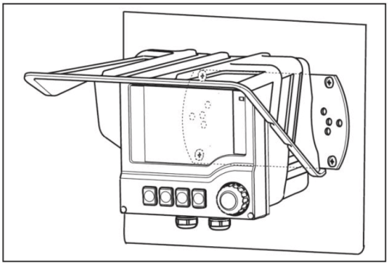
1.3 Wall Mounting
Can be equipped with a weather protection cover, suitable for outdoor or harsh environments.
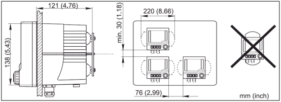
1.4 Panel Mounting
Suitable for control panel cabinet installation, saving space.
2. Wiring
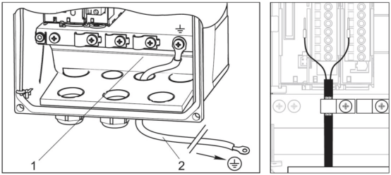
Correct wiring is the foundation for ensuring stable operation of the transmitter. Please ground the plastic housing and cable according to the figure below.
2.1 Power/Signal Wiring
2.1.1 Current Output Wiring
Supports one current output and two current outputs (optional).
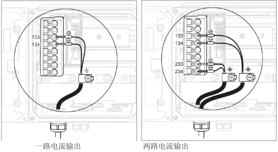
Note: The allowable supply voltage range is 12.5 to 30 VDC.
2.1.2 Bus Wiring
There are three optional wiring methods for Foundation Fieldbus and Profibus PA bus connections.
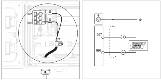
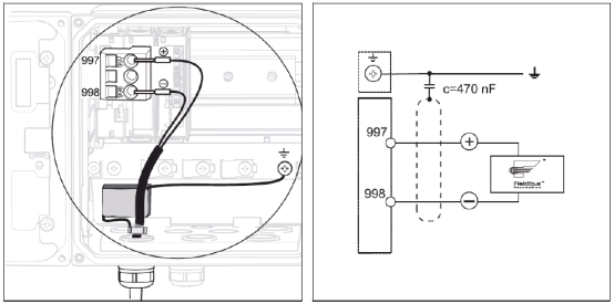
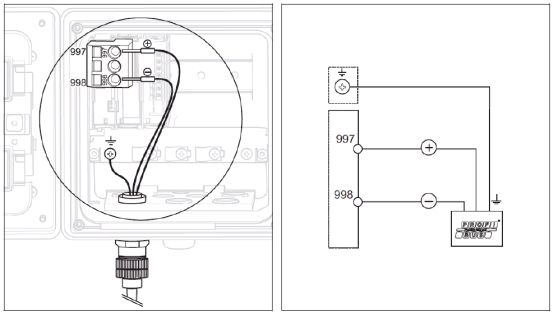
Note: The allowable supply voltage range is 9 to 32 V DC.
2.2 Sensor Wiring
Select the correct wiring method according to the sensor type.
2.2.1 Standard Analog Sensor Wiring (using CPK9 cable)
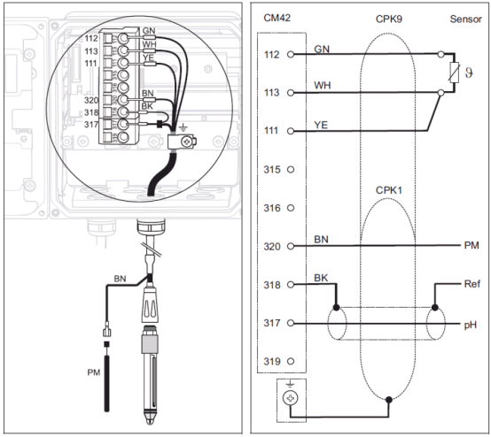
- Connect the green, white, and yellow temperature wires to terminals 112, 113, and 111 respectively.
- The core wire and black shield wire of the coaxial cable represent the measurement and reference signals respectively; connect them to terminals 317 and 318 respectively; connect the brown equipotential wire to terminal 320.
- The sensor cable shield must be grounded.
2.2.2 IsFET Analog Sensor Wiring (using CPK12 cable)
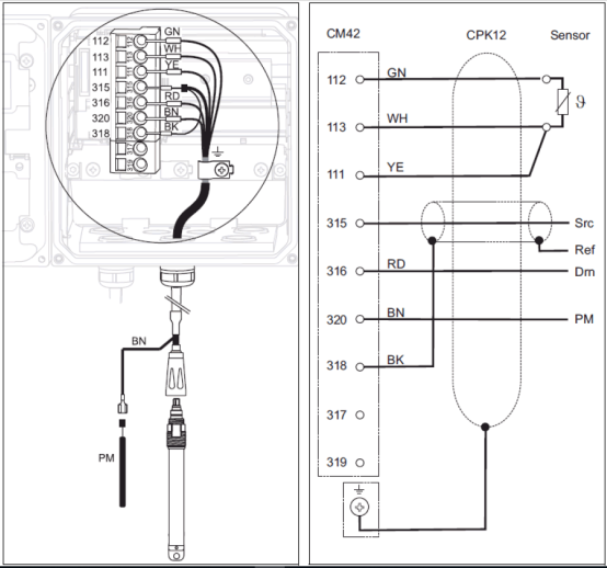
- Connect the green, white, and yellow temperature wires to terminals 112, 113, and 111 respectively.
- The core wire and black shield wire of the coaxial cable represent the measurement and reference signals respectively; connect them to terminals 315 and 318 respectively; connect the red wire to terminal 316; connect the brown equipotential wire to terminal 320.
- The sensor cable shield must be grounded.
2.2.3 Memosens Digital Sensor Wiring
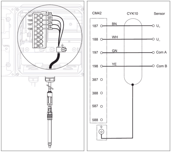
- Connect the four cable wires brown, white, green, and yellow to terminals 187, 188, 197, and 198 respectively.
- The sensor cable shield must be grounded.
Note: Ensure that all cable glands are tightened and sealed.
3. Keypad Functions
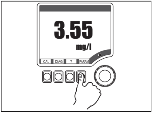
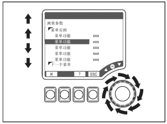
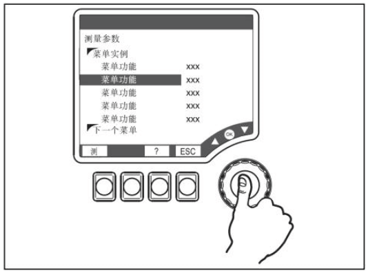
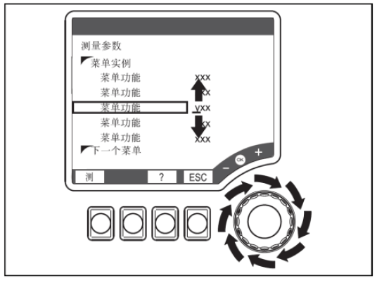
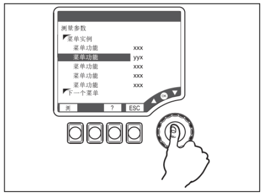
The CM42 transmitter uses intuitive keypad operation. The specific functions are as follows:
- Press soft key: directly select menu
- Rotate browser: move the cursor within the menu
- Press browser: select function
- Rotate browser: change value
- Press browser key: accept new value
4. Settings
Necessary parameter settings must be made before commissioning.
4.1 Measuring Range Setting
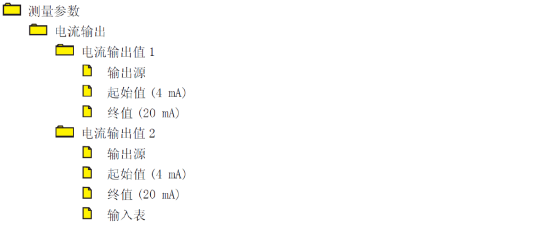
Set the "start value" and "end value" under the "Measurement parameter/Current output" menu. The specific menu location is as follows:
4.2 Buffer Solution Setting
If the user uses E+H original buffer solutions, there is no need to modify the factory default settings; otherwise, enter the menu "Measurement parameter/Sensor module/Calibration settings/Buffer recognition", change the factory default setting "Fixed" to "Manual", and enter the pH values of the two buffer solutions in the menu "Measurement parameter/Sensor module/Calibration settings/Buffer x".
4.3 Transmitter Reset
Under the "Diagnostics/Maintenance service/Factory default settings" menu, select "Factory default settings". The device will restart, and all settings will be reset to factory settings.
5. Calibration
Enter the "Calibration" menu, select "2-point calibration", and complete calibration according to the menu prompts. The main steps are as follows:
- Place the sensor in calibration solution 1 to start the first calibration point; "Running" is displayed.
- Remove the sensor from calibration solution 1 and rinse it with water.
- Place the sensor in calibration solution 2 to start the second calibration point; "Running" is displayed.
- After successful calibration, the slope and zero point are displayed, showing whether the calibration is valid. Select "Store data to adjust" or "Discard data".
6. Common Error Codes
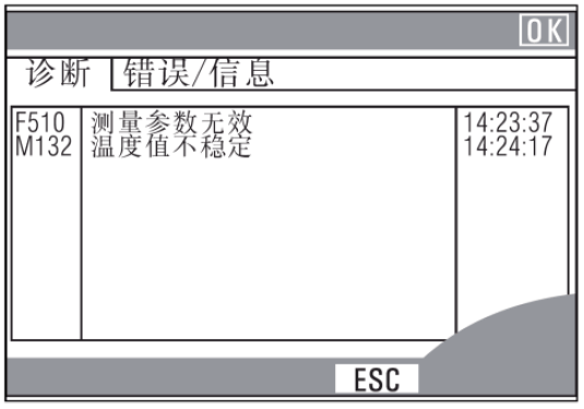
The transmitter continuously performs self-monitoring. If the device detects an error, a red alarm LED lights up. Information about the error can be read in the "Diagnostics/Error messages" menu. An example is as follows:
7. Sensor Maintenance
Regular maintenance can extend sensor life and ensure measurement accuracy.
- Regularly clean the pH sensor: The cleaning interval depends on the operating conditions. Recommended methods are as follows: If the sensor has oil film adhesion, use an appropriate detergent to remove it, such as alcohol, acetone, etc. For lime or metal hydroxide adhesion, dissolve it with 3% dilute hydrochloric acid and then rinse thoroughly with clean water. For sulfide adhesion (flue gas desulfurization or wastewater treatment plants), clean with a mixture of 3% dilute hydrochloric acid and thiourea, then rinse thoroughly with water. For protein adhesion (food industry), clean with a mixture of 0.5% dilute hydrochloric acid and saturated pepsin, then rinse thoroughly with water. If the diaphragm of the reference sensor is blocked, use a keyhole file to remove the blockage. (Not applicable to CPS11 and CPS91 sensors.) Use a soft brush to remove contamination on the ORP platinum ring, and use a soft cloth to remove contamination on the ORP gold pin. Chemical cleaning solutions must never be used on ORP sensors.
- Regularly perform two-point calibration of the pH sensor: The calibration interval depends on the operating conditions.
- pH sensor storage: pH sensors must not be exposed to air for long periods and must be stored moist. After prolonged drying, it is recommended to place the sensor in pH=7 buffer solution or 3 mol/l saturated KCl for more than 1 day to activate the sensor.