
Prosonic 93 Installation
I. Installation Position
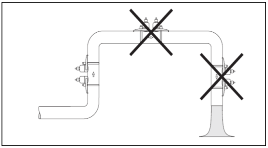
Installation position: A full pipe in the measurement pipeline is a prerequisite for correct flowmeter measurement. Install the sensor on an upward pipe whenever possible.
Note!
Gas accumulation or bubble formation in the measuring pipe will increase measurement error.
Therefore, avoid the following installation positions in the pipeline:
●The highest point of the pipeline. Gas tends to accumulate.
●Directly above a downward-draining pipe. A non-full pipe condition is likely to occur.
II. Installation Direction
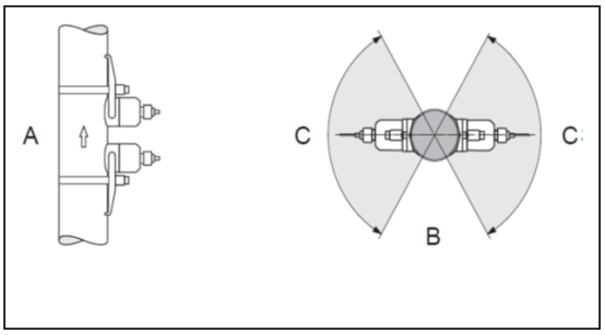
A Recommended installation direction, with fluid flowing upward
B Recommended installation range in horizontal pipes
C Recommended installation angle, max. 120°
Vertical pipe: When the sensor needs to be installed on a vertical pipe, it is recommended to select a pipe with fluid flowing from bottom to top (View A). With this installation direction, when the fluid in the pipe is stationary, entrained solid media will settle and gas will rise, away from the sensor. The pipe can be completely self-draining without solid adhesion. Horizontal pipe: When the sensor needs to be installed on a horizontal pipe, it is recommended to install it within the area shown in View B to avoid the influence of gas and air accumulation at the top of the pipe and sediment at the bottom of the pipe on the measurement.
III. Upstream and Downstream Straight Pipe Sections
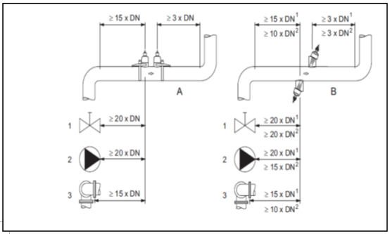
Upstream and downstream straight pipe sections: If possible, the sensor installation position should preferably avoid pipe fittings such as valves, tees, and elbows. It is recommended to observe the following upstream and downstream straight pipe section length requirements to ensure measurement accuracy. Top view of upstream and downstream straight pipe sections
A Clamp-on type
B Insertion type
1 = Valve for single-path measurement
2 = Valve for dual-path measurement
1 Valve
2 Pump
3 Two pipe elbows in different planes
IV. Sensor Selection and Installation Position
1. Installation Path
Generally, the following two sensor installation positions are used:
●Sensor installation position for single-path measurement: The two sensors are installed on opposite sides of the pipe.
●Sensor installation position for dual-path measurement: The two sensors are installed on the same side of the pipe.
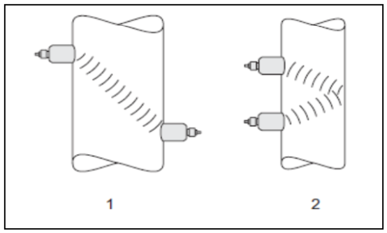
Top view of sensor installation positions
1 Sensor installation position for single-path measurement
2 Sensor installation position for dual-path measurement
2. Sensor Installation Method:
The number of acoustic signal propagation paths depends on the sensor type, nominal pipe diameter, and pipe wall thickness. The following sensor installation methods are recommended:
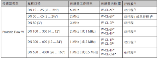
1) For clamp-on sensors, the dual-path measurement installation position is recommended. The dual-path measurement installation position is the simplest and most appropriate installation method; even if operation is only allowed on one side of the pipe, the entire measurement system can be installed. However, under certain specific working conditions, the single-path measurement installation position is more suitable for the sensor. For example:
●Some plastic pipes with wall thickness > 4 mm (0.16 in)●Composite material (e.g., GRP) pipes●Lined pipes●Acoustically damped fluid measurement
2) When sensors need to be installed on small-diameter pipes (DN 65 / 2 1/2' or smaller), if Prosonic Flow W sensors are used for measurement, the installation spacing may be too small to meet the sensor installation spacing requirements for dual-path measurement. In this case, the single-path measurement sensor installation position must be used.
3) For composite material (e.g., GRP) pipes, some lined pipes, pipes with wall thickness > 10 mm (0.4"), or when highly acoustically damped fluid flow measurement is required, it is recommended to use sensors with an operating frequency of 0.5 MHz. In this case, the single-path measurement sensor installation position is recommended.
4) Insertion-mounted Prosonic Flow W sensors use the single-path measurement sensor installation position.
5) Sensors with an operating frequency of 6 MHz are suitable for measuring media with flow velocities ≤ 10 m/s (32.8 ft/s).
3. Installation Accessories
Before installation, the required sensor installation spacing must be determined in advance. The installation spacing depends on the fluid type, pipe material, and actual pipe diameter. The transmitter has built-in sound velocity parameters for the common fluids, pipe materials, and pipe lining materials listed in the table below:
3.1 Built-in Table
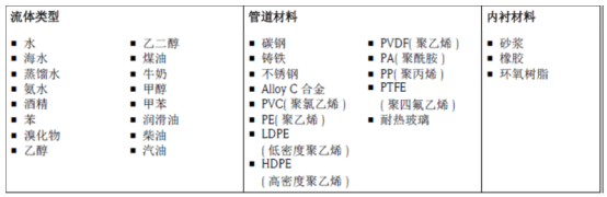
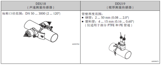
If the actual working conditions differ from the information listed in the table above and the user cannot determine the propagation speed of sound waves in the actual fluid/pipe material, use the DDU18 sensor for sound velocity measurement and the DDU19 sensor for pipe wall thickness measurement.
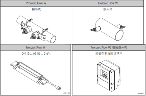
3.2 Installation Bracket and 93 Transmitter
4. Dual-Channel Measurement
The transmitter has two independently operating measurement channels (Measurement Channel 1 and Measurement Channel 2). A pair of sensors can be connected to each measurement channel. The two measurement channels operate independently of each other while being controlled by the transmitter. The dual-channel measurement mode is suitable for the following measurement applications:
●Dual-channel measurement: Flow measurement at two independent measurement points
●Dual-path measurement: Redundant flow measurement at a single measurement point
4.1 Dual-Channel Measurement
The measurement parameters in the two measurement channels can be processed and displayed separately. With dual-channel measurement, the following measurement parameters can be output:
●Measured value of each measurement channel (outputs independent of each other)
●Difference between the two measured values
●Sum of the two measured values
The two measurement channels can be configured separately to set and select the display parameters, output parameters, sensor type, and installation type for each measurement channel.
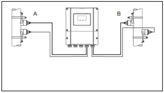
Schematic diagram of dual-channel measurement: Two pairs of sensors are installed at two independent measurement points.
A Measurement Channel 1: Sensor installation position for dual-path measurement
B Measurement Channel 2: Sensor installation position for single-path measurement
4.2 Dual-Path Measurement
Dual-path measurement is used for redundant flow measurement at a single measurement point. The measurement parameters in the two measurement channels can be processed and displayed separately. With dual-path measurement, the following measurement parameters can be output:
●Measured value of each measurement channel (outputs independent of each other)
●Average of the two measured values
The measured value "averaging" function provides more stable measured values. This function is suitable for measurement under non-ideal conditions (e.g., when the upstream straight pipe section is short).
The two measurement channels can be configured separately to set and select the display parameters, output parameters, sensor type, and installation type for each measurement channel.
In dual-path measurement mode, it is usually not necessary to configure the two measurement channels separately. However, in certain special measurement applications, the two measurement channels need to be configured separately to balance the influence of an asymmetrical system structure on the measurement.

Schematic diagram of dual-path measurement: Two pairs of sensors are installed at the same measurement point.
A Measurement Channel 1 and Measurement Channel 2: Sensor installation position for dual-path measurement
B Measurement Channel 1 and Measurement Channel 2: Sensor installation position for single-path measurement
V. Sensor Fixing Methods are as follows:
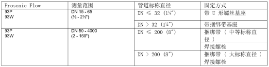
1. Install the sensor base with U-shaped screws
Sensor: Prosonic Flow 93P and Prosonic Flow 93W (DN 15-65 / 1/2-2 1/2"), installed on pipes with nominal diameter DN ≤ 32 (1 1/4").
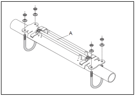
Install Prosonic Flow P base with U-shaped screws (DN 15-65
/ 1/2-2 1/2")
1. Disconnect the sensor from the sensor base.
2. Position the sensor base on the pipe.
3. Insert the U-shaped screws into the sensor base and lubricate the threads appropriately.
4. Screw the nuts onto the U-shaped screws.
5. Adjust the base to the correct position and tighten the nuts evenly.
Warning!
If the nuts of the U-shaped screws are tightened too much, plastic or glass pipes may be damaged! When working on plastic or glass pipes, it is recommended to use metal shims (located on the opposite side of the sensor).
2. Install the sensor base using strapping bands
Sensor: Prosonic Flow 93P and Prosonic Flow 93W (DN 15-65 / 1/2-1/2"), installed on pipes with nominal diameter DN > 32 (1 1/4").
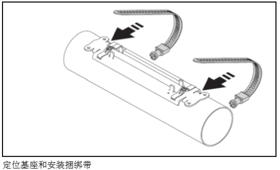
1. Disconnect the sensor from the sensor base.
2. Position the sensor base on the pipe, route the strapping band around the sensor base and the pipe, taking care not to twist it.
4. Insert the end of the strapping band into
5. Pull the strapping band as tight as possible by hand, push the strapping band lock tensioning screw upward.
6. Adjust the sensor base to the correct position.
7. Press down the tensioning screw to tighten the strapping band so that it cannot slip.
8. If necessary, shorten the strapping band and trim the cut edge.
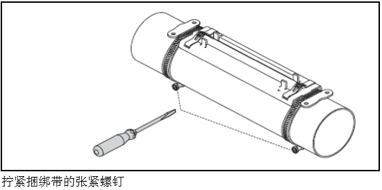
Warning!
Risk of injury. After shortening the strapping band, trim the cut edge to prevent the formation of sharp edges.
3. Pre-install the strapping band (medium nominal diameter)
Sensor: Prosonic Flow 93P and Prosonic Flow 93W (DN 50-4000 / 2-160), installed on pipes with nominal diameter DN ≤ 200 (8").
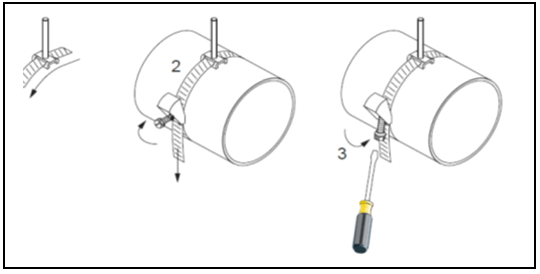
1) Mounting bolt 2) Strapping band 3) Tensioning screw
Installation steps for the first strapping band
1. Install the mounting bolt on the strapping band.
2. Wrap the strapping band around the pipe, taking care not to twist it.
3. Insert the end of the strapping band through the strapping band lock (push the tensioning screw upward).
4. Pull the strapping band as tight as possible by hand.
5. Adjust the strapping band to the required position.
6. Press down the tensioning screw to tighten the strapping band so that it cannot slip.
Installation steps for the second strapping band
7. Follow the operating steps for the first strapping band (steps 1-7). Only slightly tighten the second strapping band to facilitate final installation. The strapping band must be able to move for final adjustment.
8. If necessary, shorten the strapping band and trim the cut edge.
4. Pre-install the strapping band (large nominal diameter)
Sensor: Prosonic Flow 93P (DN 50-4000 / 2-160"), Prosonic Flow 93W, installed on pipes with nominal diameter DN > 200 (8").
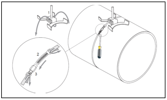
Pre-install the strapping band: Pipe diameter DN > 200 (8") 1 Center positioning plate with mounting bolt 2 Strapping band 3 Tensioning screw
1. Measure the pipe circumference.
2. Cut the strapping band to a certain length (pipe circumference + 10 cm (3.94")), and trim the cut edge.
Installation steps for the first strapping band
3. Fix the center positioning plate and mounting bolt together onto the strapping band.
4. Wrap the strapping band around the pipe, taking care not to twist it.
5. Insert the end of the strapping band through the strapping band lock (push the tensioning screw upward).
6. Pull the strapping band as tight as possible by hand.
7. Adjust the strapping band to the required position.
8. Press down the tensioning screw to tighten the strapping band so that it cannot slip.
Installation steps for the second strapping band
9. Follow the steps for the first strapping band (steps 3-8). Only slightly tighten the second strapping band to facilitate final installation. The strapping band must be able to move for final adjustment.
5. Install welded bolts
Sensor: Prosonic Flow 93P (DN 50-4000 / 2-160), Prosonic Flow 93W, installed on pipes with nominal diameter DN 50-4000 (2-160).
Steps
The welded bolts must be fixed according to the calculated installation spacing, which is the same as the mounting bolts used with strapping bands. The following sections describe how to align the mounting bolts for different installation methods and measurement methods:
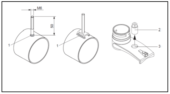
Use welded bolts 1 Weld seam 2 Fixing nut 3 Bolt hole maximum diameter: 8.7 mm (0.34")
●Prosonic Flow P (DN 50-4000 / 2-160)
●Installation for single-path measurement
●Installation for dual-path measurement
●Prosonic Flow W
●Installation for single-path measurement
●Installation for dual-path measurement
The sensor base is fixed using fixing nuts with standard ISO M6 metric threads. If other screws are to be used to fix the base, a sensor base with a detachable fixing nut must be used (order number: 93WAx-xxxxxxxxx).
6. Installation of Prosonic Flow P and Prosonic Flow 93W (DN 15-65 / 1/2-2 1/2")
Prerequisites
Installation distance (sensor spacing)
●Sensor base installed Material
The following materials are required for installation:
●Sensor (including adapter cable)
●Connecting cable to the transmitter
●Couplant for acoustic coupling between the sensor and the pipe
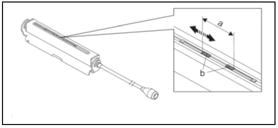
1. Adjust the sensor installation spacing according to the determined sensor spacing value. Move the sensor by pressing down slightly.
2. Apply a uniform layer of couplant (approximately 0.5-1 mm / 0.02-0.04" thick) on the sensor contact surface.
3. Mount the sensor housing on the sensor base. Adjust the sensor installation spacing according to the sensor spacing value a) Sensor spacing b) Sensor contact surface
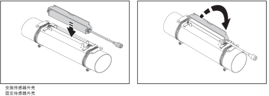
4. Fix the sensor housing with the mounting bracket.
Note!
- If necessary, use screws/nuts or lead seals (not standard supply items) to fix the base and sensor housing.
- The mounting bracket can only be removed using auxiliary tools.
5. Connect the connecting cable to the adapter cable. The installation process is now complete. The sensor can now be connected to the transmitter via the connecting cable.
7. Installation of Prosonic Flow P (DN 50-4000 / 2"-
160")
7.1 Installation of Prosonic Flow P for single-path measurement
Steps
1. Prepare two measuring wire lines:
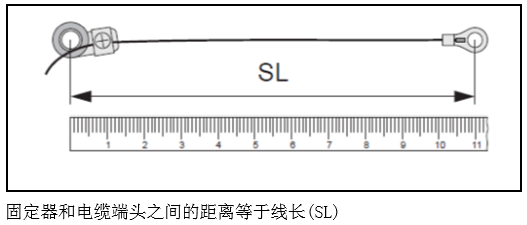
- Place the end piece and the fixer, ensuring that the distance between them equals the wire length (SL).
- Screw the fixer onto the measuring wire line.
Note: SL: WIRE LENGTH wire length
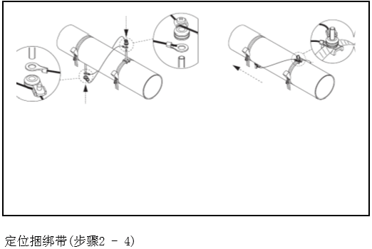
2. Route the first measuring wire line:
- Attach the fixer to the mounting bolt of the fixed strapping band.
- Route "clockwise" around the pipe.
- Place the end of the measuring wire line over the mounting bolt of the movable strapping band.
3. Route the second measuring wire line:
- Attach the end piece to the mounting bolt of the fixed strapping band.
- Route the measuring wire line "counterclockwise" around the pipe.
- Place the fixer over the mounting bolt of the movable strapping band.
4. Move the movable strapping band (including the mounting bolt) until both measuring wires are evenly tensioned, then tighten this strapping band so that it cannot slip.
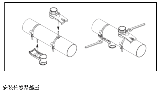
5. Loosen the fixer screws on the measuring wire lines and remove the measuring wire lines from the mounting bolts.
6. Mount the sensor base on each mounting bolt and tighten firmly with the fixing nuts.
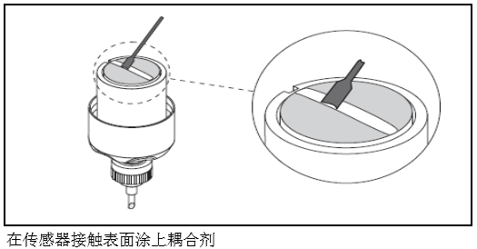
7. On the sensor contact surface, apply a uniform layer of couplant from the groove through the center to the opposite edge, approximately 1 mm (0.04") thick.
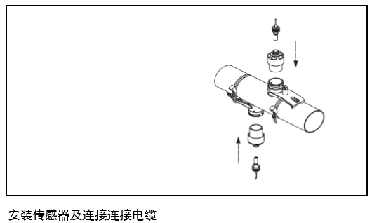
8. Insert the sensor into the sensor base.
9. Press the sensor onto the sensor base and rotate until a "click" sound engages the sensor housing - arrows  "close") are aligned with each other.
10. Connect the connecting cable to each sensor. The installation process is now complete. Use the connecting cable to connect the sensors to the transmitter.
7.2 Installation of Prosonic Flow P for dual-path measurement (DN 50-600 / 2"-24")
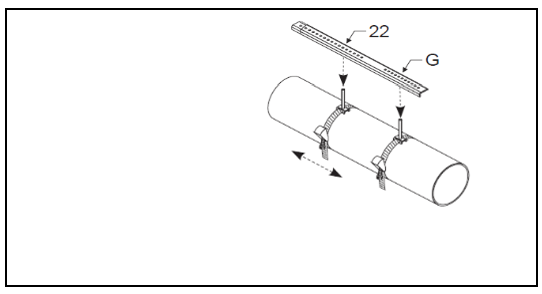
Use the mounting rail ruler to determine the distance (e.g., "POSITION SENSOR G22" / "Sensor position G22")
Steps
1. Use the mounting rail ruler to position the strapping bands.
- Place the hole on the mounting rail ruler marked with the specific letter "POSITION SENSOR / Sensor position" over the mounting bolt of the fixed strapping band.
- Adjust the position of the movable strapping band and place the hole marked with the specific value "POSITION SENSOR / Sensor position" over the mounting rail ruler.
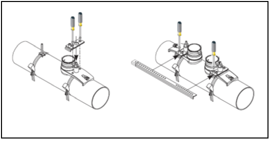
2. Tighten the movable strapping band so that it cannot slip.
3. Remove the mounting rail ruler from the mounting bolts.
4. Mount the sensor base on each mounting bolt and tighten firmly with the fixing nuts.
5. Screw the mounting rail ruler fixing bracket onto the relevant sensor base.
6. Screw the mounting rail ruler onto the sensor base.
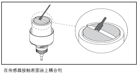
7. On the sensor contact surface, apply a uniform layer of couplant from the groove through the center to the opposite edge, approximately 1 mm (0.04") thick.
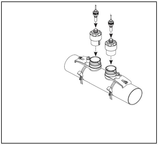
Install the sensor and connecting cable
8. Insert the sensor into the sensor base.
9. Press the sensor onto the sensor base and rotate until: a "click" sound engages the sensor housing - arrows  "close") are aligned with each other.
10. Connect the connecting cable to each sensor. The installation process is now complete. Use the connecting cable to connect the sensors to the transmitter.
8. Installation of Prosonic Flow W (clamp-on type)
8.1 Installation of Prosonic Flow W for single-path measurement
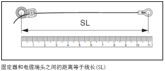
Steps
1. Prepare two measuring wire lines:
- Place the end piece and the fixer, ensuring that the distance between them equals the wire length (SL).
- Screw the fixer onto the measuring wire line.
Note: SL: WIRE LENGTH wire length
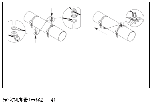
2. Route the first measuring wire line:
- Attach the fixer to the mounting bolt of the fixed strapping band.
- Route "clockwise" around the pipe.
- Place the end of the measuring wire line over the mounting bolt of the movable strapping band.
3. Route the second measuring wire line:
- Attach the end piece to the mounting bolt of the fixed strapping band.
- Route the measuring wire line "counterclockwise" around the pipe.
- Place the fixer over the mounting bolt of the movable strapping band.
4. Move the movable strapping band (including the mounting bolt) until both measuring wires are evenly tensioned, then tighten this strapping band so that it cannot slip.
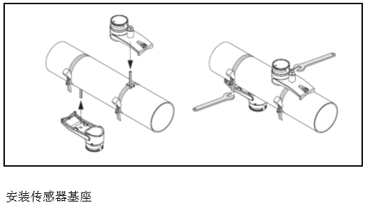
5. Loosen the fixer screws on the measuring wire lines and remove the measuring wire lines from the mounting bolts.
6. Mount the sensor base on each mounting bolt and tighten firmly with the fixing nuts.
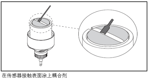
7. On the sensor contact surface, apply a uniform layer of couplant from the groove through the center to the opposite edge, approximately 1 mm (0.04") thick.
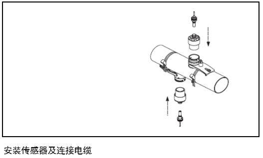
8. Insert the sensor into the sensor base.
9. Press the sensor onto the sensor base and rotate until: a "click" sound engages the sensor housing - arrows ("close") are aligned with each other.
10. Connect the connecting cable to each sensor. The installation process is now complete. Use the connecting cable to connect the sensors to the transmitter.
8.2 Installation of Prosonic Flow W for dual-path measurement
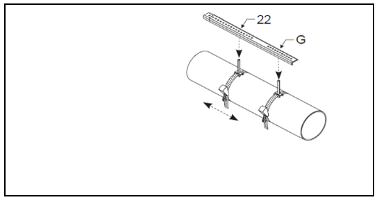
Use the mounting rail ruler to determine the distance (e.g., "POSITION SENSOR G22" / "Sensor position G22")
Steps
1. Use the mounting rail ruler to position the strapping bands. Place the hole on the mounting rail ruler marked with the specific letter "POSITION SENSOR / Sensor position" over the mounting bolt of the fixed strapping band.
- Adjust the position of the movable strapping band and place the hole marked with the specific value "POSITION SENSOR / Sensor position" over the mounting rail ruler.
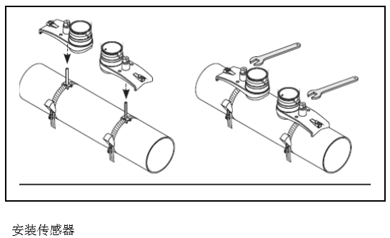
2. Tighten the movable strapping band so that it cannot slip.
3. Remove the mounting rail ruler from the mounting bolts.
4. Mount the sensor base on each mounting bolt and tighten firmly with the fixing nuts.
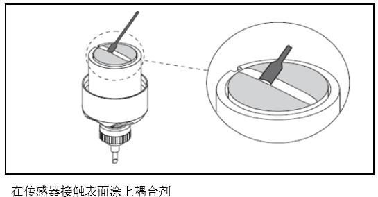
5. On the sensor contact surface, apply a uniform layer of couplant from the groove through the center to the opposite edge, approximately 1 mm (0.04") thick.
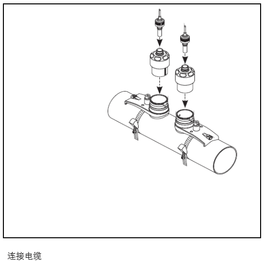
6. Insert the sensor into the sensor base.
7. Press the sensor onto the sensor base and rotate until:
- A "click" sound engages the sensor housing
- Arrows  "close") are aligned with each other.
8. Connect the connecting cable to each sensor. The installation process is now complete. Use the connecting cable to connect the sensors to the transmitter.
9. Installation of Prosonic W Insertion Sensors
9.1 Insertion Installation for Single-Channel Measurement
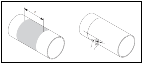
1. Determine the installation area (e) of the pipe:
- Installation position
- Upstream/downstream straight pipe sections
- Space requirement for the measurement point: approximately 1x pipe diameter
2. Mark the centerline of the pipe installation position and mark the position of the first hole (hole diameter: 65 mm / 2.56")
Note! The centerline length is greater than the hole!
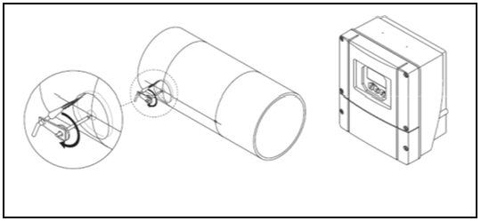
3. Cut the first hole, e.g., with a plasma cutting machine if the thickness of the measuring pipe wall is unknown
4. Determine the sensor distance
Note! Determine the sensor distance as follows:
Operate with buttons, run the Quick Setup through the "Sensor Installation" menu in Quick Setup. The sensor distance is displayed in the SENSOR DISTANCE function. Before running the 'Sensor Installation' Quick Setup, the transmitter must be installed and connected to the power supply.
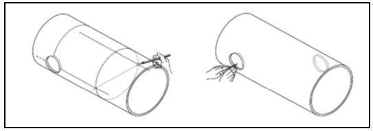
5. Draw the sensor distance from the first hole
6. Draw the centerline on the back of the pipe
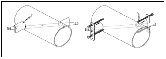
7. Mark the hole on the centerline on the back of the pipe
8. Cut the second hole and prepare the sensor base for welding the hole (chamfering, cleaning, etc.)
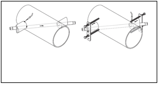
9. Insert the sensor base, adjust the welding depth, fix the two sensor bases with a special tool for insertion depth adjustment (optional), then use a pull rod to align them. The sensor base must be flush with the inside of the pipe.
10. Tack weld the two sensor bases
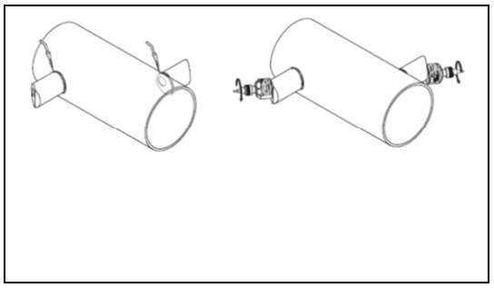
11. Weld the sensor bases
12. Check the distance between the hole and the path length again
Note! Determine the path length as follows:
Operate with buttons, run the Quick Setup through the "Sensor Installation" menu in Quick Setup. The path length is displayed in the PATH LENGTH function. Before running the 'Sensor Installation' Quick Setup, the transmitter must be installed and connected to the power supply.
13. Screw the sensor onto the sensor base by hand. If a tool is used, the maximum allowable torque is 30 Nm.
14. Insert the sensor connector and tighten manually.
9.2 Insertion Installation for Dual-Channel Measurement
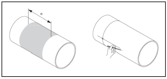
1. Determine the installation area (e) of the pipe:
- Installation position
- Upstream/downstream straight pipe sections
- Space requirement for the measurement point: approximately 1x pipe diameter
2. Mark the centerline of the pipe installation position
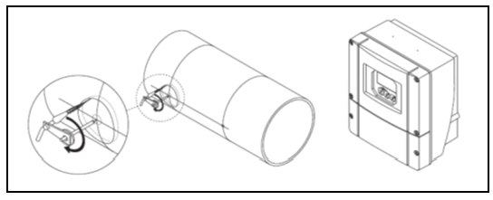
3. At the probe holder installation position, mark the arc length (b) on one side of the centerline. Typically, the arc length is approximately 1/12 of the pipe circumference. Mark the first hole (hole diameter approximately 81 to 82 mm / 3.19 to 3.23")
4. Cut the first hole, e.g., with a plasma cutting machine if the thickness of the measuring pipe wall is unknown
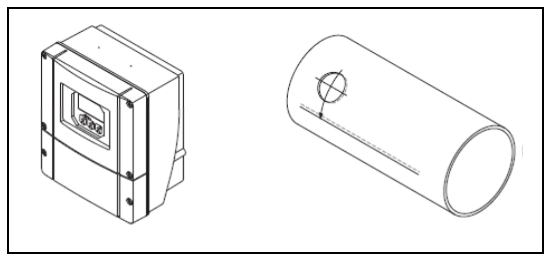
5. Determine the probe distance between the hole distance (probe distance) and the arc length
Note!
Determine the sensor distance as follows:
Operate with buttons, run the Quick Setup through the "Sensor Installation" menu in Quick Setup. The sensor distance is displayed in the SENSOR DISTANCE function (6886) and the arc length is displayed in the ARC LENGTH function. Before running, the transmitter must be installed and connected to the power supply.
6. Correct the centerline using the arc length
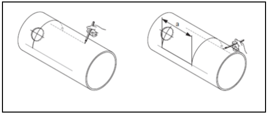
7. Design and draw the corrected centerline on the other side of the pipe (half the pipe circumference)
8. Mark the sensor distance on the centerline and design the centerline on the back of the pipe
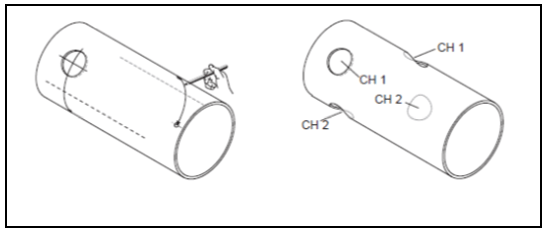
9. Extend the arc length on each side of the centerline and mark the holes
10. Drill the holes and prepare the holes for welding the sensor bases (chamfering, cleaning, etc.)
Note!
The holes prepared for the sensor bases always appear in pairs (CH1-CH1 and CH2-CH2)
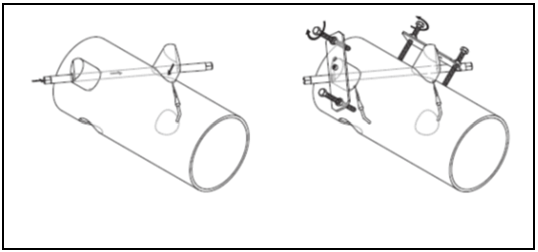
11. Insert the sensor bases into the first pair of holes, align them with a telescopic rod (alignment straight tool), tack weld the sensor bases, then permanently weld the two sensor bases.
Note!
Align the pull rod; the two guide clamps must be tightened on the sensor bases.
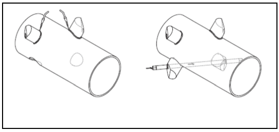
12. Weld the two sensor bases
13. Check the path length, sensor distance, and arc length again
Note!
These distances can be obtained in Quick Setup. If there are deviations, pay attention to these when commissioning the measurement point and enter the correction factor.
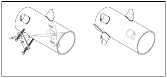
14. Insert the second pair of sensors onto the sensor bases and weld the two sensor bases
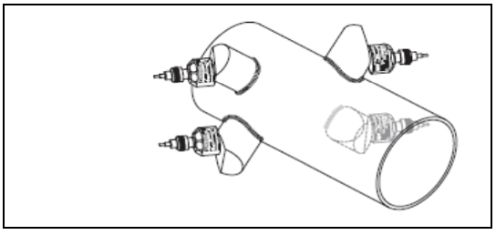
15. Screw the sensor onto the sensor base by hand. If a tool is used, the maximum allowable torque is 30 Nm.
16. Insert the sensor connector and tighten manually.