
1. Check the Nameplate
Before wiring, the transmitter nameplate information must be checked to ensure that parameters such as power supply and input/output are consistent with on-site requirements.
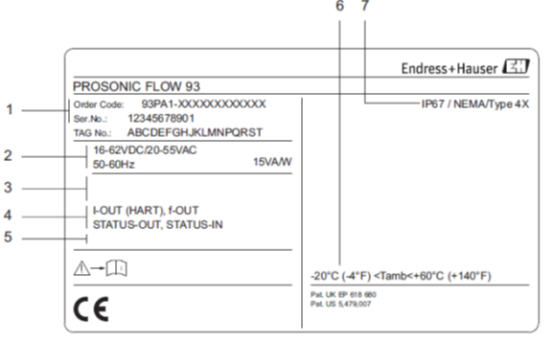
- Order number/serial number: Used to identify the product model and version.
- Power supply: 16~62 V DC / 20~55 V AC / 50~60 Hz, power consumption 15 VA/W.
- Reserved additional information: Optional according to order.
- Available input/output: I-OUT (HART) current output, f-OUT frequency output, RELAY relay output, STAT-IN status input (auxiliary input).
- Information specific to special products: Such as explosion-proof rating, etc.
- Permissible ambient temperature range: Ensure the working environment meets the requirements.
- Protection class: Such as IP67, etc.
2. Nameplate in the Connection Compartment of Prosonic Flow 93W
The nameplate inside the connection compartment provides more detailed configuration and terminal assignment information and should be read carefully before wiring.
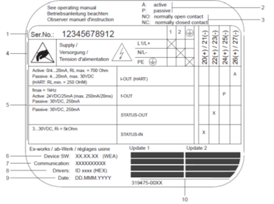
- Serial number: Consistent with the external nameplate.
- Possible configuration of current input: Such as 4~20 mA, etc.
- Possible relay configuration: Normally open/normally closed, etc.
- Terminal assignment: Power supply cable: 85~260 V AC, 20~55 V AC, 16~62 V DC; Terminal No. 1: L1 (AC) / L+ (DC); Terminal No. 2: N (AC) / L- (DC).
- Input and output signals: Configuration and terminal assignment (20~27).
- Currently installed device software version: Such as Dev.01.
- Installed communication mode: Such as HART, PROFIBUS PA, etc.
- Current communication software information: Device version and device description, such as Dev.01 / DD 01 for HART.
- Installation date: Record commissioning time.
- List of currently refreshed information from 6 to 9: For easy maintenance.
3. Power Supply Wiring
The electrical connection diagram of the transmitter is as follows. The maximum cross-sectional area of the connection cable is 2.5 mm² (14 AWG).
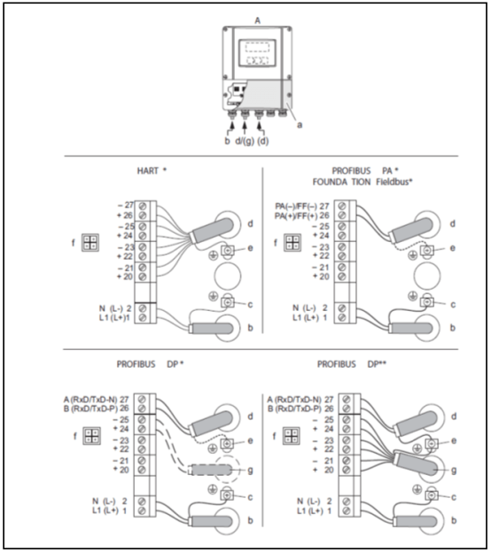
- a Connection compartment cover
- b Power supply cable: 85~260 V AC / 20~55 V AC / 16~62 V DC
- Terminal No. 1: L1 for AC, L+ for DC
- Terminal No. 2: N for AC, L- for DC
- c Protective ground terminal
- d Signal cable: Refer to "Terminal Assignment"; Fieldbus cable:
- Terminal No. 26: DP (B) / PA (+) / FF (+), with reverse polarity protection
- Terminal No. 27: DP (A) / PA (-) / FF (-), with reverse polarity protection
- e Ground terminal for signal cable shield/fieldbus cable
- f Service interface: Can connect handheld terminal FXA193 (Fieldcheck, FieldCare)
- g Signal cable: Refer to "Terminal Assignment"; External terminal cable (only for PROFIBUS DP instruments with fixed communication module): +5V, DGND
4. Terminal Assignment
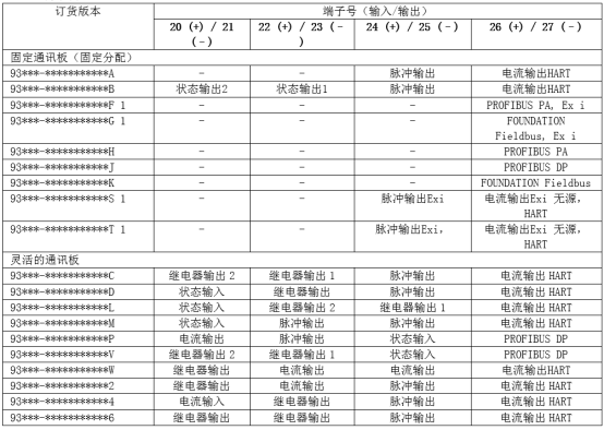
For specific terminal assignment, please refer to the figure below to ensure that power supply, signal, and communication lines are connected correctly.
5. Sensor/Transmitter Connection Cable
When connecting the sensor and transmitter, please follow the steps below and pay attention to grounding requirements.
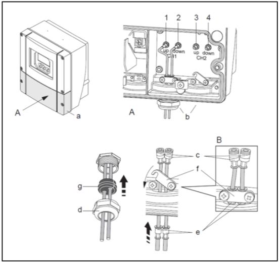
- Remove the housing cover (a) of the connection compartment.
- Remove the blind cover at the cable entry (b).
- Pass the two connection cables (c) of channel 1 through the cable gland (d).
- Pass the two connection cables of channel 1 through the cable entry (b) into the connection compartment of the transmitter.
- Connect the cable sheaths (e) of the two connection cables to the ground terminal (f) (see Figure B for details).
- Tighten the ground terminal (f) to firmly secure the two cable sheaths (e).
- Tighten the ground terminal (f). Note! Prosonic Flow P (DN 15-65 / 1/2-2½") is grounded via the cable gland.
- Cable connection:
- Channel 1 upstream = 1, channel 1 downstream = 2
- Channel 2 upstream = 3, channel 2 downstream = 4
- Use a suitable tool (e.g., a large screwdriver) to pry the rubber seal (g) along the side groove and secure the two connection cables in place.
- Place the rubber seal (g) into the cable entry (b).
- Tighten the cable gland (d).
- Install the housing cover (a) on the connection compartment and secure it with screws.
View and component description for connecting the sensor/transmitter connection cable:
- 1 Sensor cable connector, channel 1 upstream
- 2 Sensor cable connector, channel 1 downstream
- 3 Sensor cable connector, channel 2 upstream
- 4 Sensor cable connector, channel 2 downstream
- a Connection compartment cover
- b Cable entry (with cable gland for connecting two connection cables)
- c Connection cable
- d Cable gland
- e Cable protective sleeve
- f Ground terminal (only Prosonic Flow P DN 50-4000 (2-160"), for Prosonic Flow P DN 15-65 (1/2-2½") grounding steps refer to the description below)
- g Rubber seal
Grounding for Prosonic Flow P DN 15-65 (1/2-2½"): Grounding via cable gland.
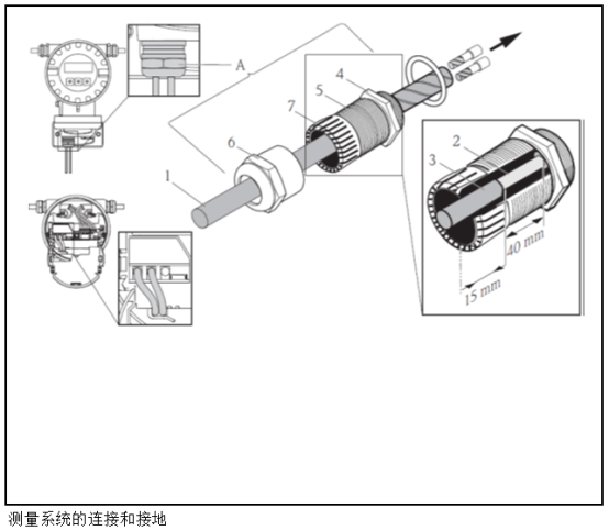
- 1 Cable sheath
- 2 Exposed braided shield (prefabricated)
- 3 Rubber sleeve
- 4 Internal contact point for grounding on this surface (not externally inspectable)
- 5 Cable gland
- 6 Cable gland cap
- 7 Grounding mechanism
Grounding steps:
- Screw the cable gland (5) into the transmitter housing.
- Pass the sensor connection cable through the cable gland cap (6).
- Push the sensor connection cable into the transmitter housing. Align the outer end of the rubber sleeve (3) with the end of the cable gland (5)/grounding mechanism (7). This ensures that the cable gland: a) seals; b) after the cable is secured, it can be properly grounded to the internal contact point (4) of the transmitter housing.
- Tighten the cable gland cap (6) clockwise. Since external inspection is not possible, it is essential to follow this instruction.
Note: Cables marked in red indicate the sensor "up"; cables marked in blue indicate the sensor "down".
Note: The cable gland can be removed from the cable by loosening and removing the cable gland cap. Then use tweezers to retract the grounding mechanism (7). Do not apply too much force when retracting (excessive force will damage the shield). It may be necessary to turn the cable gland clockwise to advance the grounding mechanism further, thereby releasing the internal hook of the grounding mechanism from the lock. Remove the cable gland cap again. Then try again to retract it with tweezers.