
1. Check the Nameplate
Before wiring, carefully check the nameplate information of the Promag 50 electromagnetic flowmeter to ensure the device meets application requirements. The nameplate contains key parameters such as power supply, output configuration, and protection class, which are the basis for correct wiring.
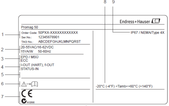
1. Order Code and Serial Number
Record the order code and serial number for device identification and spare parts ordering.
2. Power Supply and Power Consumption
Confirm the power supply type: 220VAC or 24VDC, and note the power frequency and power consumption. Incorrect power supply may damage the device.
3. Additional Information
- EPD/MSU: Empty pipe detection electrode
- ECC: Electrode cleaning function
4. Input/Output Configuration
- I-OUT (HART): Current output (supports HART protocol)
- f-OUT: Frequency output
- STATUS-IN: Status input
5. Special Product Information
Reserved special product information, please verify according to actual requirements.
6. Device Documentation
Comply with the documentation requirements supplied with the device to ensure compliant installation.
7. Additional Information on Device Version
Includes certifications, certificates, etc., which affect installation and operating environment.
8. Permissible Ambient Temperature Range
Ensure the operating environment temperature is within the permissible range to avoid affecting accuracy and service life.
9. Protection Class
Select an appropriate installation method according to the protection class (e.g., IP67).
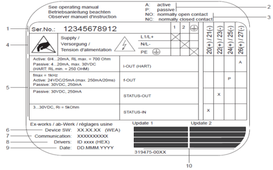
Detailed Nameplate Additional Information
- Serial Number: Unique device identifier.
- Current Output Configuration: A-active, P-passive.
- Relay Configuration: NO-normally open, NC-normally closed.
- Terminal Assignment: Terminal 1-AC L1/DC L+, Terminal 2-AC N/DC L-.
- Configuration of Terminals 20-27: Defined according to output configuration.
- Software Version: Currently installed software version.
- Communication Type: e.g., HART, PROFIBUS PA, etc.
- Current Communication Software Information: Device version and device description.
- Installation Date: Device installation time.
- Update Date: Update date for points 6 to 9.
2. Wiring of Separate Sensor and Transmitter
For the separate Promag 50, the sensor and transmitter are connected via a dedicated signal cable. Correct connection ensures stable signal transmission.
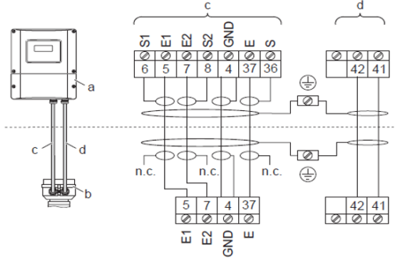
Wiring Components
- a: Wall-mounted instrument housing connection part
- b: Sensor connection housing cover
- c: Signal cable
- d: Coil current cable (n.c. not connected)
Cable Colors and Terminal Numbers
| Color | Terminal Number |
|---|---|
| Brown | 5/6 |
| White | 7/8 |
| Green | 4-GND |
| Yellow | 37/36 |
The cable shield must be properly grounded to reduce interference.
3. Transmitter Wiring
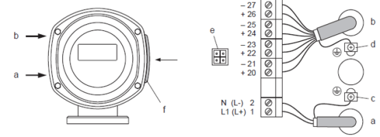
Transmitter wiring includes power supply, signal output, and grounding. Depending on the housing type (aluminum housing, stainless steel housing, or wall-mounted), the wiring method differs slightly, but terminal functions are the same.
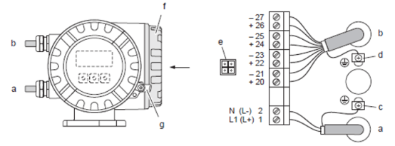
Aluminum Housing Transmitter Wiring
Maximum cable inner diameter 2.5 mm².
- a: Power supply cable: Terminal 1-AC L1/DC L+, Terminal 2-AC N/DC L-
- b: Signal cable: Terminals 20-27
- c: Protective ground terminal
- d: Signal cable shield ground terminal
- e: Service interface (Fieldcheck, FieldCare)
- f: Terminal compartment cover
- g: Internal hex screw cover lock
Stainless Steel Housing Transmitter Wiring
Maximum cable inner diameter 2.5 mm².
- a: Power supply cable: Terminal 1-AC L1/DC L+, Terminal 2-AC N/DC L-
- b: Signal cable: Terminals 20-27
- c: Protective ground terminal
- d: Signal cable shield ground terminal
- e: Service interface (Fieldcheck, FieldCare)
- f: Terminal compartment cover
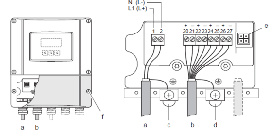
Wall-Mounted Transmitter Wiring
Maximum cable inner diameter 2.5 mm².
- a: Power supply cable: Terminal 1-AC L1/DC L+, Terminal 2-AC N/DC L-
- b: Signal cable: Terminals 20-27
- c: Protective ground terminal
- d: Signal cable shield ground terminal
- e: Service interface (Fieldcheck, FieldCare)
- f: Terminal compartment cover
4. Terminal Assignment
Terminal assignment defines the function of each terminal. Correct connection is key to ensuring measurement accuracy. The following describes the terminal functions of the Promag 50.
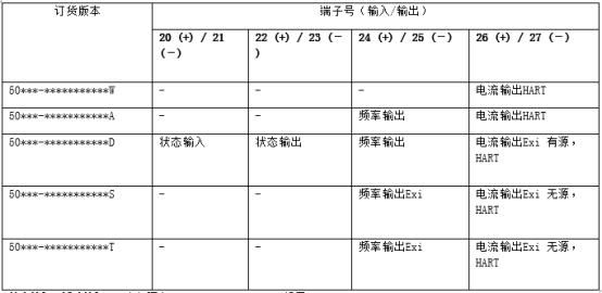
Status Input (Auxiliary Input)
Electrically isolated, 330VDC, Ri=5kΩ, configurable.
Status Output
Open collector, max.30V DC/250mA, electrically isolated, configurable.
Frequency Output (Passive)
Open collector, electrically isolated, 30V DC/250mA. Frequency output: full scale frequency 2..1000Hz (fmax=1250Hz), on/off ratio 1:1, pulse width max.2s. Pulse output: pulse value and pulse polarity selectable, pulse width adjustable (0.5...2000ms).
Current Output (Active/Passive)
Electrically isolated, active: 0...20mA, passive: 4...20mA. See nameplate for specific configuration.
Always refer to the device documentation during wiring to ensure safety and performance.