Promag 400 Electromagnetic Flowmeter Wiring Overview
Promag 400 is an electromagnetic flowmeter launched by Endress+Hauser and is widely used in industrial flow measurement. Correct wiring is the foundation for ensuring measurement accuracy and stable equipment operation. This article will introduce its wiring steps, terminal definitions, and precautions in detail.
Preparation Before Wiring
Tools and Materials
- Screwdriver (Phillips and flathead)
- Wire stripper
- Multimeter
- Cable (select according to specifications)
- Waterproof connector (if required)
Safety Precautions
- Ensure the power supply is turned off and attach a warning sign.
- Comply with local electrical codes.
- Avoid operating in humid environments.
Terminal Assignment and Functions
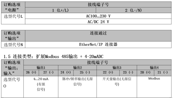
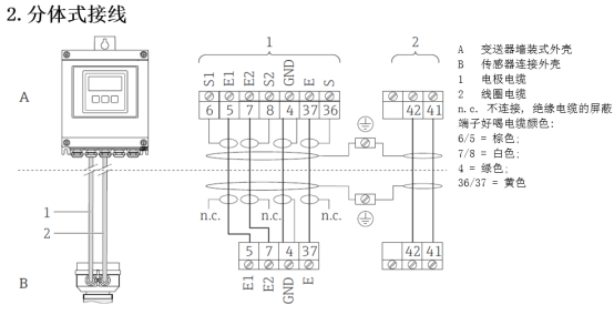
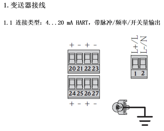
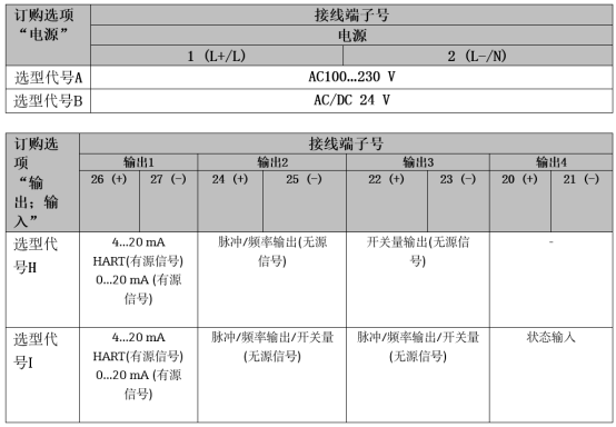
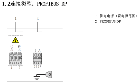
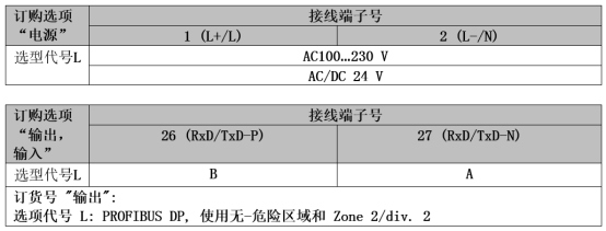
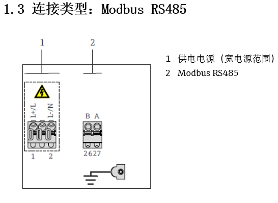
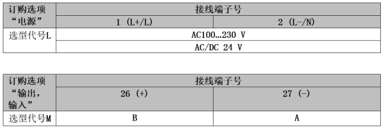
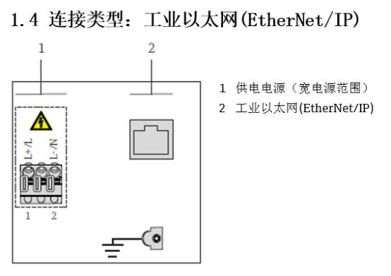
The wiring terminals of the Promag 400 are located inside the transmitter, and the specific assignment is shown in the table below. Please confirm according to the nameplate and wiring diagram.
| Terminal Number | Function | Cable Type |
|---|---|---|
| 1, 2 | Power input (L, N) | AC 85-260V or DC 20-55V |
| 3, 4 | Current output (4-20mA) | Shielded twisted pair |
| 5, 6 | Pulse/frequency output | Shielded twisted pair |
| 7, 8 | Digital input | Shielded twisted pair |
| 9, 10 | Relay output | Shielded twisted pair |
Wiring Steps
Step 1: Open the Transmitter Housing
Use a screwdriver to loosen the screws on the housing cover and carefully open the housing. Be careful not to damage the sealing ring.
Step 2: Introduce the Cable
Introduce the cable through the cable gland and ensure the gland is well sealed. Leave sufficient length for wiring.
Step 3: Connect the Power Cable
- Strip the power cable to an appropriate length to expose the copper core.
- According to the terminal assignment, connect the L wire to terminal 1 and the N wire to terminal 2.
- Tighten the terminal screws to ensure good contact.
Step 4: Connect the Signal Cable
- Use shielded twisted pair to connect the current output (terminals 3, 4).
- Connect the pulse/frequency output, digital input, and relay output as required.
- Ensure the shield layer is grounded at one end to avoid interference.
Step 5: Inspection and Closing
- Check whether all wiring is firm and there is no short circuit or open circuit.
- After confirming there are no errors, replace the housing and tighten the screws.
Cable Specifications and Shielding
To ensure signal quality, it is recommended to use cables that meet the following specifications:
- Power cable: cross-sectional area ≥ 1.5 mm²
- Signal cable: cross-sectional area ≥ 0.5 mm², shield coverage ≥ 85%
- Cable outer diameter must match the cable gland
Common Issues and Precautions
- Power supply voltage: must match the nameplate to avoid damaging the equipment.
- Grounding: the flowmeter must be reliably grounded, with grounding resistance < 10 Ω.
- Interference: keep signal cables away from power cables and avoid parallel routing.
- Waterproofing: ensure the cable gland and housing are sealed to prevent water ingress.
Post-Wiring Verification
After wiring is completed, perform the following checks:
- Use a multimeter to check whether the power supply voltage is normal.
- Check whether the current output corresponds to the flow value.
- Observe whether the device display is normal and there are no alarms.
Summary
Correct wiring is the key to stable operation of the Promag 400. Following the steps and precautions in this article can ensure safe and reliable wiring. If you have any questions, please refer to the official manual or contact technical support.