
Overview of the Promass 80 Low Flow Cutoff Function
Low Flow Cutoff is an important function of the Promass 80 Coriolis mass flowmeter, used to suppress false flow output when the fluid in the pipe is nearly stationary. When the measured value is below the set threshold, the transmitter forces the flow to zero, preventing zero-point drift caused by vibration, bubbles, or installation stress from being misinterpreted as actual flow.
Properly setting the low flow cutoff value can significantly improve stability in scenarios such as batch control, filling metering, and trade settlement. This article uses the Promass 80 series transmitter as an example to explain on-site operation steps and parameter recommendations.
Preparation Before Configuration
Necessary Tools and Permissions
- Confirm that the transmitter is powered on and in measurement mode.
- Prepare the operating panel keys or FieldCare/FieldMate commissioning tools.
- Obtain the user password (if write protection is enabled).
- Record the current cutoff value for restoration in case of abnormalities.
Confirm Process Parameters
Before configuration, it is necessary to clarify the minimum actual flow and zero-point noise level in the pipeline. Typically, the cutoff value is set at 0.5% to 2% of the full scale, or slightly higher than the zero-point fluctuation value observed on site. The specific value should be determined based on medium viscosity, pipe diameter, and installation conditions.
Low Flow Cutoff Configuration Steps
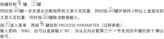
Enter the Parameter Menu
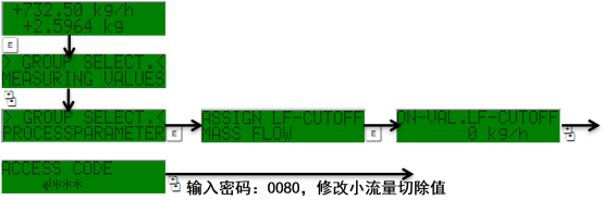
- Press the E key on the panel to enter the main menu.
- Use the +/- keys to select the "Setup" menu.
- Enter the "Process Parameter" submenu.
- Find the "Low Flow Cutoff" option.
[Click the image to enlarge]
Modify the Cutoff Value
- Press the E key to enter edit mode, and the value starts flashing.
- Use the +/- keys to adjust the cutoff value; the unit is the same as the current flow unit.
- Press the E key to confirm the input.
- Check whether the displayed value meets the process requirements.
[Click the image to enlarge]
Save and Exit
- Press the E key to return to the previous menu.
- Select "Save" to write the parameters.
- Press the E key to confirm, and the transmitter automatically returns to measurement mode.
Parameter Recommendations and Precautions
Typical Cutoff Value Reference
| Application Scenario | Recommended Cutoff Value | Description |
|---|---|---|
| General process monitoring | 0.5%~1% of full scale | Balance sensitivity and stability |
| Batch filling | 1%~2% of full scale | Avoid false metering due to dripping |
| High-viscosity media | 2%~5% of full scale | Suppress zero-point noise |
| Trade settlement | Set according to verification regulations | Must comply with metrology regulations |
Key Precautions
- The cutoff value should not be too large, otherwise real low flow signals will be lost.
- The cutoff value should not be too small, otherwise zero-point fluctuations will cause false increases in the totalized value.
- After modification, a zero-point calibration should be performed to ensure a full pipe and static state.
- If the transmitter is in a write-protected state, the lock must be released first.
Troubleshooting Common Issues
Flow Still Does Not Return to Zero After Configuration
Possible causes include the pipe not being full, the presence of bubbles, or installation stress. It is recommended to check the installation direction and venting conditions, and perform zero-point calibration again if necessary.
Low Flow Signal Is Incorrectly Cut Off
If the actual minimum flow is lower than the cutoff value, the cutoff value should be appropriately reduced, or it should be confirmed whether the process truly has a continuous微小 flow. The trend chart can be used to observe zero-point noise before adjusting.
Summary
The low flow cutoff configuration of the Promass 80 is simple to operate, but the parameter selection directly affects measurement accuracy. It is recommended that engineering technicians determine the cutoff value comprehensively based on medium characteristics, pipe diameter, and process requirements, and verify zero-point stability after modification. Correct configuration can effectively improve the reliability of the flowmeter under low flow conditions.