
Promass 100/200/300/500 Installation Guide
1. Installation Location
When gas bubbles accumulate in the measuring tube, measurement errors increase. Therefore, avoid installing at the following locations in the pipeline:
- The highest point of the pipeline
- Directly above a downward draining pipeline
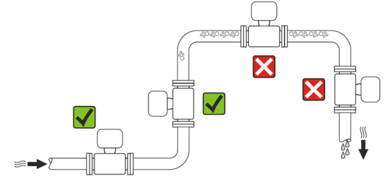
[Click image to enlarge]
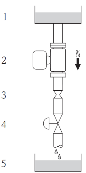
When installing the flowmeter in a downward draining pipeline, it is recommended to install an orifice plate or a section of reduced diameter pipe to prevent empty pipe conditions during measurement.
Installation in a downward draining pipeline (e.g., batch application scenarios)
[Click image to enlarge]
- 1 Supply tank
- 2 Sensor
- 3 Orifice plate
- 4 Valve
- 5 Metering tank
2. Installation Orientation
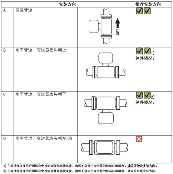
Install according to the arrow direction on the sensor nameplate, and always ensure that the arrow direction is consistent with the flow direction of the medium in the pipeline.
[Click image to enlarge]
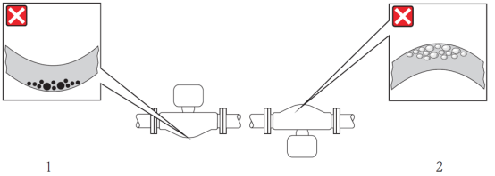
When a sensor with a bent measuring tube is placed horizontally, the installation position of the sensor must match the fluid characteristics.
[Click image to enlarge]
- 1 When measuring fluids containing solids, avoid this installation orientation: risk of solid accumulation
- 2 When measuring fluids containing gas, avoid this installation orientation: risk of gas accumulation
3. Upstream and Downstream Straight Pipe Sections
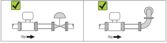
For Coriolis mass flowmeters, as long as cavitation does not occur, there is no need to consider the upstream and downstream straight pipe section lengths for fittings. For example: valves, elbows, or tees.
[Click image to enlarge]
4. Environmental and Process Requirements
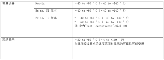
4.1 Ambient Temperature Range
[Click image to enlarge]
If installed outdoors, avoid direct sunlight, especially in warm climates.
4.2 System Pressure
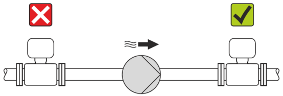
It is important to prevent cavitation, or to prevent gas entrained in the liquid from degassing.
Cavitation occurs when the pressure loss falls below the vapor pressure:
- When there are some low-boiling-point media in the liquid (e.g., hydrocarbons, solvents, liquefied gas)
- On siphon lines, ensure the system pressure is high enough to prevent cavitation and degassing
For this reason, the following installation locations are recommended:
- The lowest point of a vertical pipeline
- Downstream of the pump (no risk of vacuum)
[Click image to enlarge]
5. Special Installation Guidelines - Rupture Disc
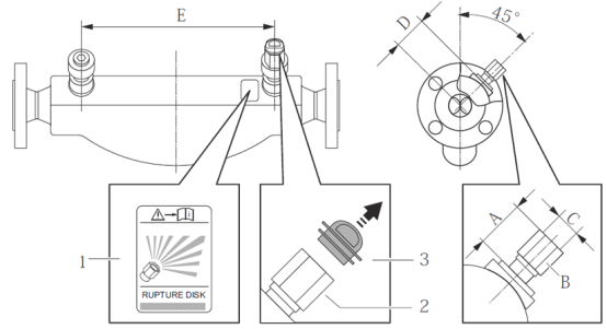
During the installation of the instrument, always ensure that the rupture disc is not damaged. There is an adhesive label above the rupture disc indicating its location. After the rupture disc has been used, the label is damaged. Therefore, the rupture disc can be visually monitored.
[Click image to enlarge]
- 1 Rupture disc label
- 2 1/2' NPT female thread, 1' across flats rupture disc
- 3 Transport protection cap
6. Zero Point Adjustment
All measuring devices are strictly factory-calibrated on the world's most advanced calibration equipment. Calibration is performed under reference operating conditions; therefore, on-site zero point adjustment is usually not required! Based on field application experience, zero point adjustment is only recommended in specific application scenarios:
- Extremely high-precision measurement of very small flows
- Under extreme process conditions or operating conditions (e.g., extremely high process temperatures or fluids with extremely high viscosity)