
Promass 100 Wiring Detailed Explanation
The Promass 100 series flowmeters offer multiple communication interfaces and housing types. Correct wiring is key to ensuring measurement accuracy and system stability. Based on official documentation, this article systematically organizes wiring terminals, transmitter connections, and pin assignments for reference by engineering and technical personnel and procurement staff.
1. Wiring Terminals and Housing Types
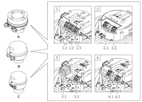
The Promass 100 offers three housing types to suit different installation environments:
- Housing Type A: Integrated instrument, aluminum housing, coated.
- Housing Type B: Integrated instrument, hygienic, stainless steel housing.
- Housing Type C: Ultra-compact integrated instrument, hygienic, stainless steel housing, with M12 instrument plug.
The terminal layout varies depending on the connection type. Common connection types include 4..20 mA HART, Modbus RS485, Industrial Ethernet (EtherNet/IP), and PROFIBUS DP. The figure below shows a typical terminal arrangement:
[Click image to enlarge]
1.1 Connection Type 1: 4..20 mA HART, Pulse/Frequency/Switch Output
- 1.1 Transmission signal: Pulse/frequency/switch output
- 1.2 Transmission signal: 4..20 mA HART
- 1.3 Power supply
1.2 Connection Type 2: Modbus RS485
- 2.1 Transmission signal
- 2.2 Power supply
1.3 Connection Type 3: Industrial Ethernet (EtherNet/IP)
- 3.1 Transmission signal
- 3.2 Power supply
1.4 Connection Type 4: PROFIBUS DP
- 4.1 PROFIBUS DP
- 4.2 Power supply
2. Transmitter Wiring
Transmitter wiring must be carried out according to the selected communication protocol. The following sections describe each connection type.
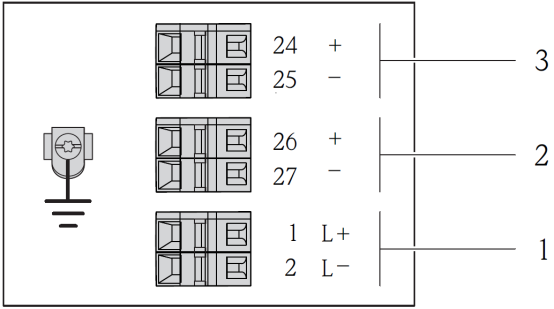
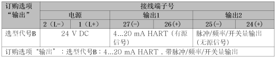
2.1 Connection Type: 4..20 mA HART, with Pulse/Frequency/Switch Output
[Click image to enlarge]
- 1 Power supply: 24V DC
- 2 Output 1: 4..20 mA HART (active signal)
- 3 Output 2: Pulse/frequency/switch output (passive signal)
[Click image to enlarge]
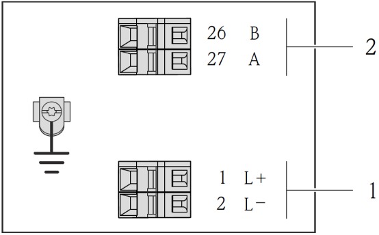
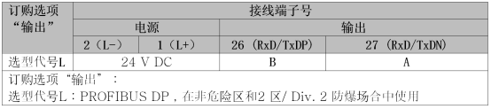
2.2 Connection Type: PROFIBUS DP
[Click image to enlarge]
- 1 Power supply: 24V DC
- 2 PROFIBUS DP
[Click image to enlarge]
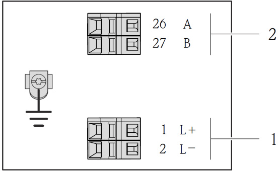
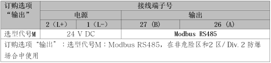
2.3 Connection Type: Modbus RS485 - Non-hazardous Area and Zone 2/Div. 2 Hazardous Area
[Click image to enlarge]
- 1 Power supply: 24V DC
- 2 Modbus RS485
[Click image to enlarge]
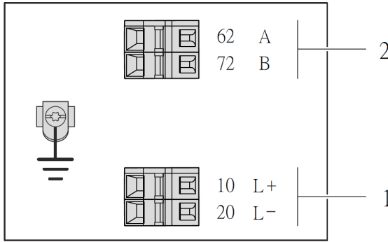
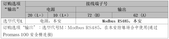
2.4 Connection Type: Modbus RS485 - Intrinsically Safe Hazardous Area
When used in an intrinsically safe hazardous area, connection must be made via the Promass 100 safety barrier.
[Click image to enlarge]
- 1 Intrinsically safe power supply
- 2 Modbus RS485
[Click image to enlarge]
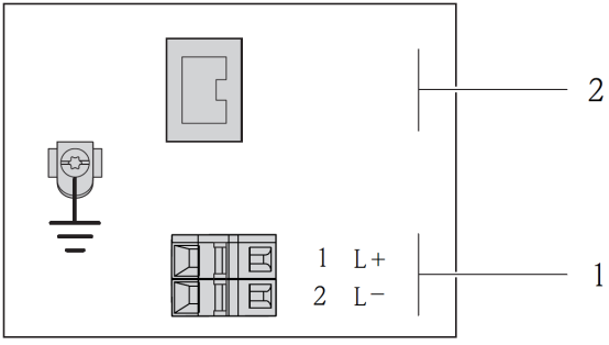
2.5 Connection Type: Industrial Ethernet (EtherNet/IP)
[Click image to enlarge]
- 1 Power supply: 24V DC
- 2 Industrial Ethernet (EtherNet/IP)

[Click image to enlarge]
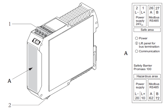
2.6 Promass 100 Safety Barrier
[Click image to enlarge]
- 1 Non-hazardous area and Zone 2/Div. 2 hazardous area
- 2 Intrinsically safe hazardous area
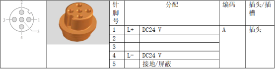
3. Pin Assignments and Instrument Plugs
The pin assignments of the instrument plug vary depending on the communication protocol. Common types are listed below.
3.1 Supply Voltage Device Plug
[Click image to enlarge]
3.2 4..20 mA HART, with Pulse/Frequency/Switch Output Transmission Signal Device Plug
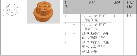
[Click image to enlarge]
3.3 PROFIBUS DP Output Transmission Signal Device Plug
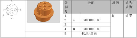
[Click image to enlarge]
3.4 MODBUS RS485 Output Transmission Signal Device Plug
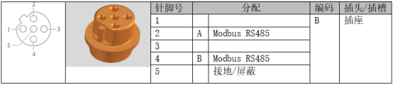
[Click image to enlarge]
3.5 Industrial Ethernet (EtherNet/IP) Transmission Signal Device Plug
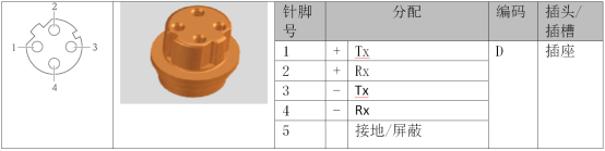
[Click image to enlarge]
Summary
Correct wiring is the foundation for ensuring reliable operation of the Promass 100 flowmeter. Users must refer to the corresponding wiring diagrams for installation based on the actual communication protocol, explosion-proof requirements, and housing type. For intrinsically safe hazardous areas, a safety barrier must be used. If in doubt, please refer to the official manual or contact technical support.