
T-mass 65 Gas Type Quick Setup Overview
The T-mass 65 thermal mass flowmeter supports flexible gas type settings and can adapt to the measurement needs of single gases or gas mixtures. By programming gas components, users can quickly switch gas types or compensate for component changes to ensure flow measurement accuracy.Gas component programming is the core function for handling non-standard gases or variable-composition operating conditions.
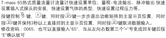
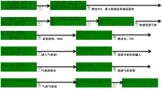
Gas Component Programming Methods
The T-mass 65 provides two gas component programming methods: single gas selection and gas mixture configuration. Users can flexibly choose according to actual operating conditions.
Single Gas Setup
- Select the required gas type from the standard gas list.
- If the gas is not in the standard list, select another suitable gas type (such as ozone).
- Use a manual correction factor for correction, or select the SPECIAL GAS option.
- The special gas option requires a factory evaluation report before it can be enabled.
Gas Mixture Setup (Up to Eight Components)
For gas mixtures, the T-mass 65 supports programming of up to eight components. Users need to enter the gas type and proportion of each component in sequence, and the flowmeter will calculate the mass flow based on the mixing ratio.
Gas Compensation Input: ANALYZER INPUT
The T-mass 65 has a gas compensation input function, which can directly read the 4-20mA output signal from an external gas analyzer and automatically update the proportions of two components in the programmed gas mixture (for example, gas type 1 and 2). This function is particularly suitable for scenarios with dynamically changing components such as biogas and can significantly improve measurement accuracy.
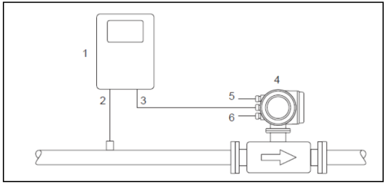
Typical Connection Configuration
| Number | Device/Signal | Description |
|---|---|---|
| 1 | Gas analyzer | Provides 4-20mA component signal |
| 2 | Gas detector | Detects gas concentration |
| 3 | 4-20mA signal | Analyzer output to T-mass 65 |
| 4 | T-mass 65 | Receives compensation signal and calculates flow |
| 5 | Power supply | Supplies power to T-mass 65 |
| 6 | Output | Flow signal output |
Configuration Steps
- Enter the CURRENT INPUT menu.
- Select ASSIGN CURRENT INPUT.
- Assign to the GAS ANALYZER function.
- Set the corresponding gas components (such as gas type 1 and 2).
Activating Gas Component Settings and Observation
The active measurement group can be set in two ways, and users can choose according to on-site conditions.
- Digital input: Configure through the status input to switch between two gas groups; select GAS GROUP.
- Manual selection: Directly activate the required gas group in the menu.
After setup is complete, the currently active gas components and flow measurement values can be observed in real time on the display.