Prowirl 72/73 Vortex Flowmeter Installation Guide
1. Installation Position Selection
A stable flow pattern of the medium is a prerequisite for accurate measurement with a vortex flowmeter. Always ensure that the arrow direction on the sensor nameplate or the housing orientation is consistent with the flow direction of the fluid in the pipeline.
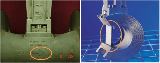
Fluid direction on the sensor body and housing orientation
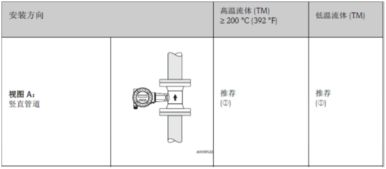
The flowmeter can be installed in any orientation in the pipeline. It is recommended to refer to the following table to select the optimal installation orientation:
1. Measuring Liquids
A vertical pipeline should be used, with the fluid flowing from bottom to top, to avoid a non-full pipe condition (refer to View A).
Caution! Measurement interruption! When measuring fluid flowing from top to bottom in a vertical pipeline, it must be ensured that the measuring tube is always in a full-pipe state to guarantee flow measurement accuracy.
2. Avoiding Overheating of Electronic Components
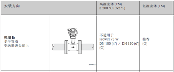
Caution! Avoid overheating of electronic components! If the fluid temperature is higher than 200 °C (392 °F), the wafer-style Prowirl 73 W (DN 100 (4") and DN 150 (6")) must not be installed in the orientation shown in View B.
To ensure that the transmitter does not exceed the maximum permissible ambient temperature, the following two installation orientations are recommended:
3. Measuring Hot Fluids
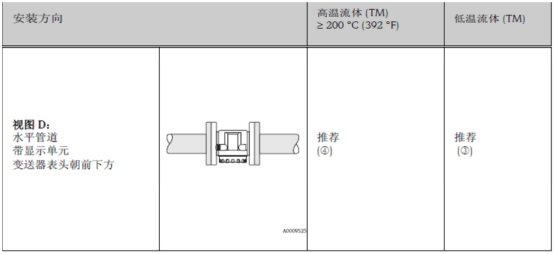
When measuring hot fluids (e.g., steam or liquids with a temperature higher than 200°C (392°F)), select installation orientation C or D.
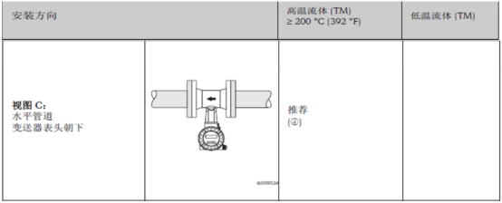
Note: When measuring saturated steam, if a large amount of condensate is present, it can cause probe damage and measurement fluctuations. It is recommended to install as shown in View B and apply proper insulation to reduce the impact on the electronic module.
4. Measuring Cold Media
When measuring cold media, select installation orientation B or D.
2. Insulation of the Piping System
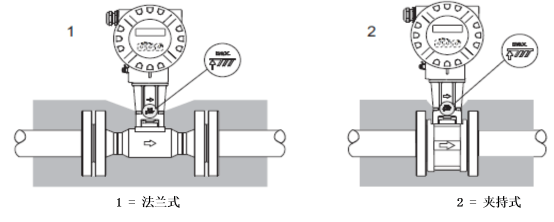
When performing insulation treatment on the piping system, be sure to expose a sufficient portion of the flowmeter housing support. The portion not covered by insulation can dissipate heat outward, preventing the internal electronic components from overheating (or overcooling). For the maximum insulation thickness, please refer to the figure below, which applies to both compact and remote versions of the instrument.
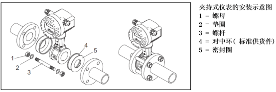
3. Installation Components for Wafer-Style Instruments
4. Upstream and Downstream Straight Pipe Length Requirements
To ensure measurement accuracy, the minimum upstream and downstream straight pipe lengths shown in the figure below must be satisfied. When two or more disturbance sources are present, it is recommended to follow the longest straight pipe length requirement.
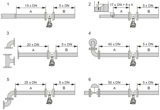

Note! If the upstream straight pipe length requirement cannot be met, it is recommended to install an Endress+Hauser special orifice flow conditioner. The flow conditioner is installed between two pipeline flanges and centered via mounting nuts. Therefore, while ensuring measurement accuracy, the upstream straight pipe length can be reduced by 10x DN.
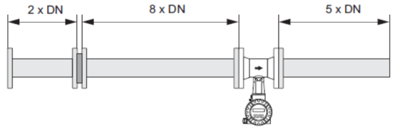
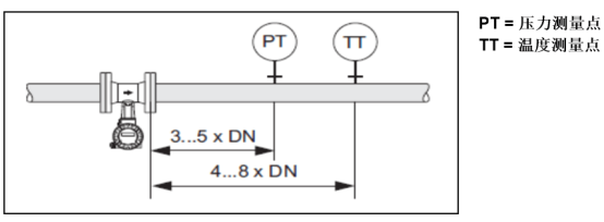
5. Downstream Straight Pipe Length with Pressure and Temperature Measurement
When pressure and temperature measurement points are installed in the downstream pipeline of the instrument, or when temperature and pressure compensation is required for installation, ensure that a sufficiently large spacing is maintained between the flowmeter and the measurement points so as not to affect the normal vortex formation of the sensor.