
1. Checking the Nameplate
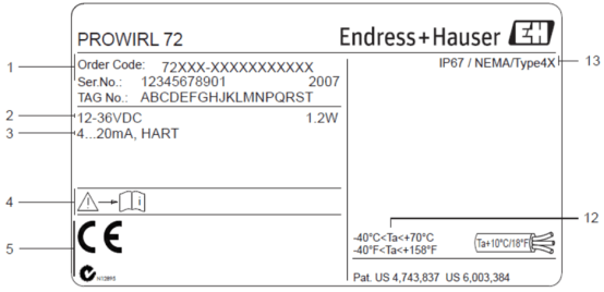
Before wiring, be sure to check the instrument nameplate information to ensure it is consistent with the design. The nameplate contains the following key information:
- Order code/serial number: Used to identify the instrument model and version.
- Power supply, power consumption: Confirm the power supply type and power requirements.
- Current output: Additional information for 4-20 mA.
- Device documentation: Related technical materials.
- Certificates, approvals, and other information: Reserved area, which may include explosion-proof certification, etc.
- Ambient temperature: The ambient temperature range applicable to the instrument.
- Protection class: Such as IP66/IP67, etc.
2. Power Supply Wiring
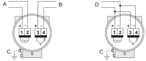
Power supply wiring differs depending on the communication protocol. Please refer to the figure below for wiring.
Terminal Definitions
- A. HART: Power supply, current output. For PROFIBUS PA: 1=PA+, 2=PA-; for FOUNDATION Fieldbus (FF): 1=FF+, 2=FF-.
- B. Optional pulse output: Not applicable to PROFIBUS PA and FOUNDATION Fieldbus (FF). Can be configured as a status output; frequency output only applicable to Prowirl 73; PFM output (pulse/frequency modulation) only applicable to Prowirl 72, and must be used with flow computer RMC621 or RMS621.
- C. Ground terminal for remote instruments: Used for equipotential bonding.
- D. Only applicable to Prowirl 72: PFM output terminals, connected to flow computer RMC621 or RMS621.
3. Wiring Between the Sensor and Transmitter of a Remote Vortex Flowmeter
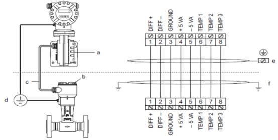
Remote instruments require a dedicated signal cable to connect the sensor and transmitter. The electrical connection diagram is shown below.
Wiring Instructions
- a = Transmitter terminal compartment cover
- b = Sensor terminal box cover
- c = Connecting cable (signal cable)
- d = Equipotential terminals of the sensor and transmitter
- e = Connect the shield to the ground terminal on the transmitter housing
- f = Connect the shield to the strain-relief cable clamp in the terminal box
Wire Core Colors (in accordance with DIN 47100)
| Terminal No. | Wire Core Color |
|---|---|
| 1 | White |
| 2 | Brown |
| 3 | Green |
| 4 | Green |
| 5 | Gray |
| 6 | Pink |
| 7 | Blue |
| 8 | Red |
Armored signal cable is optional. It is suitable for static installation and fixed cable installation, as well as flexible installation conditions with no tensile load and no related constraints, allowing the cable to move freely. The cable can be installed in dry and wet areas, as well as in soil and outdoor environments.
4. Electrical Connection of the HART Input
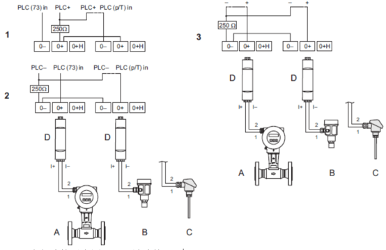
The HART input can be used to connect external sensors or a PLC. The specific wiring method depends on the application scenario.
Connection Options
- Electrical connection diagram, "+" terminal connected to PLC: The dashed line indicates optional wiring when only the Prowirl 73 signal is connected to the PLC.
- Electrical connection diagram, "-" terminal connected: The dashed line indicates optional wiring when only the Prowirl 73 signal is connected to the PLC.
- Electrical connection diagram without PLC: The dashed line indicates wiring without external components (e.g., recorder, display unit, Fieldgate, etc.).
Legend
- A = Prowirl 73
- B = Excitation sensor (Cerabar M)
- C = Temperature sensor (Omnigrad TR10) or other external measuring instrument (HART communication active, burst mode active)
- D = Active barrier (RN221N)