
TMT80 Temperature Transmitter Overview
The TMT80 is a universal temperature transmitter that supports thermocouple and RTD inputs and outputs a two-wire 4-20mA signal. Its power supply and signal share two wires, with a supply range of 8-35V DC. Correct wiring is the prerequisite for ensuring measurement accuracy and stable operation.
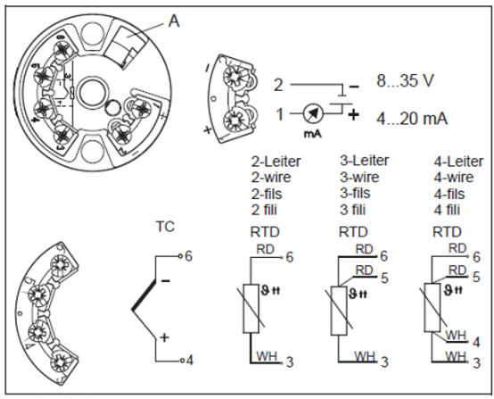
Power Supply and Signal Wiring
The TMT80 uses a two-wire loop power supply, with power and signal sharing terminals 1+ and 2-.
- 1+: Connect to the positive pole of the power supply (8-35V DC)
- 2-: Connect to the negative pole of the power supply, and also serves as the 4-20mA signal output loop
Note: The power supply polarity must not be reversed, otherwise the transmitter will not work.
Sensor Wiring Methods
The TMT80 can be connected to various temperature sensors, and the wiring terminals differ depending on the sensor type.
Thermocouple Wiring
- Connect the positive pole of the thermocouple to terminal 4+
- Connect the negative pole of the thermocouple to terminal 6-
Use compensation wires matching the thermocouple graduation and pay attention to polarity.
RTD Wiring
RTDs (such as PT100) support 2-wire, 3-wire, and 4-wire configurations. The wiring methods are as follows:
| RTD Type | Terminals | Description |
|---|---|---|
| 2-wire | 3 and 6 | Connect the two lead wires to 3 and 6 respectively |
| 3-wire | 3, 5, 6 | Connect one end to 3, and the two wires from the other end to 5 and 6 |
| 4-wire | 3, 4, 5, 6 | Connect the two wires from one end to 3 and 4, and the two wires from the other end to 5 and 6 |
3-wire and 4-wire configurations can effectively eliminate the influence of lead resistance and are recommended for high-precision applications.
Wiring Steps and Precautions
- Confirm the sensor type (thermocouple or RTD) and wiring configuration.
- Connect the sensor wires according to the corresponding relationships above based on the type.
- Connect the power supply wires to terminals 1+ and 2-, observing polarity.
- Check that all connections are secure, with no short circuits or open circuits.
- After power-on, check whether the output current is normal (4-20mA).
Note: Disconnect the power supply before wiring to avoid live operation. Using shielded cables can improve interference resistance.