
TMT85 Temperature Transmitter Wiring Overview
The TMT85 temperature transmitter is a commonly used temperature measurement instrument in industrial sites. Whether its wiring is correct directly affects measurement accuracy and system stability. This article explains the TMT85 wiring terminals, power and signal loops, and sensor connection methods for the reference of engineering technicians and procurement personnel.
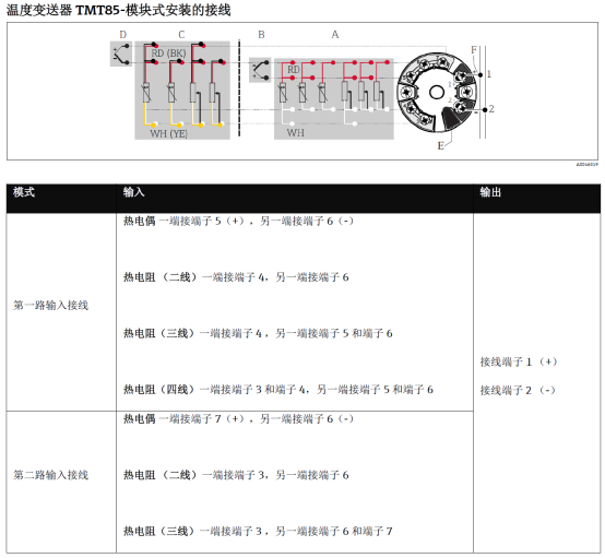
Wiring Terminal Definitions and Functions
The TMT85 usually uses pluggable wiring terminals, with a clear correspondence between terminal numbers and functions. Before wiring, carefully check the nameplate and manual to confirm the positions of the power, signal, and sensor terminals.
Common Terminal Functions
- Power terminals (+/-): Connect to a 24V DC loop power supply, paying attention to polarity.
- Signal output terminals: Output a 4-20mA analog signal or HART digital signal.
- Sensor input terminals: Connect to temperature sensing elements such as resistance temperature detectors (RTDs) or thermocouples (TCs).
Wiring Steps and Operation Methods
Follow the steps below for TMT85 wiring to effectively avoid common errors and improve installation efficiency.
- Power-off confirmation: Turn off the power to ensure no live operation during wiring.
- Open the cover for wiring: Open the transmitter housing to expose the wiring terminals.
- Power wiring: Connect the positive and negative poles of the 24V DC power supply to the corresponding terminals, noting that polarity must not be reversed.
- Signal wiring: Connect the 4-20mA signal line to the output terminals and connect it to the control system or display instrument.
- Sensor wiring: Connect to the corresponding input terminals according to the sensor type (RTD/TC), paying attention to three-wire or four-wire connections.
- Check and tighten: Confirm that all wiring is secure and there is no risk of short circuits from exposed copper wires.
- Power-on test: Restore power and observe whether the output signal is normal.
Comparison of Sensor Connection Methods
Different sensor types correspond to different wiring methods. The table below compares the characteristics of common connection methods.
| Sensor Type | Wiring Method | Characteristics |
|---|---|---|
| Resistance temperature detector (RTD) | Two-wire/three-wire/four-wire | Three-wire can compensate for lead resistance; four-wire has the highest accuracy |
| Thermocouple (TC) | Two-wire | Requires compensation wire; pay attention to cold junction compensation |
| Remote sensor | Extension wire connection | Need to consider wire resistance and interference; shielded wire is recommended |
Wiring Precautions and Common Issues
During wiring, pay attention to the following points to ensure long-term stable operation of the TMT85.
- Power polarity: Reverse connection may damage the transmitter.
- Signal loop: Ensure the loop load is within the allowable range to avoid signal distortion.
- Sensor type: It must be correctly configured in the transmitter, otherwise the output will be incorrect.
- Shielding and grounding: Shielded twisted-pair cable is recommended for signal lines, with the shield grounded at one end.
- Environmental protection: After wiring, ensure the housing is sealed to prevent moisture and dust from entering.
Summary
Correct wiring is the foundation for reliable operation of the TMT85 temperature transmitter. Following terminal definitions, standardized wiring steps, and paying attention to sensor matching and shielded grounding can effectively improve measurement accuracy and system stability. During actual wiring, always refer to the product manual and on-site specifications.