
Overview of TMT142B Temperature Transmitter Wiring
The TMT142B temperature transmitter is a commonly used temperature measurement instrument in industrial sites, and the quality of its wiring directly affects measurement accuracy and system stability. Correct wiring requires clarifying terminal functions, power supply type, and signal loops. Based on typical applications, this article explains the wiring key points step by step.
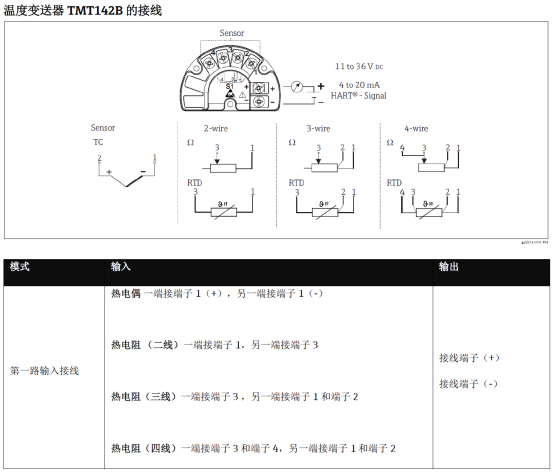
Terminal Definitions and Functions
The TMT142B usually uses pluggable terminals, and the functions of each terminal are shown in the table below. Before wiring, be sure to check the product nameplate and manual.
| Terminal No. | Marking | Function Description |
|---|---|---|
| 1 | + | Power supply positive (usually 24V DC) |
| 2 | - | Power supply negative / signal loop negative |
| 3 | + | Sensor input positive |
| 4 | - | Sensor input negative |
Power and Signal Loop Wiring
- Two-wire system: The power supply and signal share a pair of wires. Terminal 1 connects to the positive pole, and terminal 2 connects to the negative pole and is connected in series with a load resistor.
- Four-wire system: The power supply and signal are independent. Terminals 1 and 2 connect to the power supply, terminals 3 and 4 connect to the sensor, and the output signal is connected separately.
- Ensure that the power supply voltage is within the range of 12~45V DC to avoid overvoltage damage to the transmitter.
Sensor Connection Methods
Depending on the sensor type (resistance temperature detector RTD or thermocouple TC), the wiring method differs:
- Resistance temperature detector (RTD): Three-wire or four-wire connection is recommended to eliminate the effect of lead resistance. In a three-wire connection, two wires of the same color connect to terminal 3, and the other connects to terminal 4.
- Thermocouple (TC): The positive pole connects to terminal 3, and the negative pole connects to terminal 4. Compensation wires must be used.
- Sensor cables should use shielded wires, and the shielding layer should be grounded at one end.
Wiring Steps and Precautions
Follow the steps below to ensure safe and reliable wiring:
- Disconnect the power supply and confirm that there is no electricity on site.
- Strip the cable outer sheath to expose an appropriate length of conductor and avoid short circuits.
- Connect the power wires and sensor wires according to the terminal definitions, and tighten the screws.
- After checking that the wiring is correct, turn on the power supply and observe the transmitter indicator light or output signal.
- Use a multimeter to measure the output current and verify whether it corresponds to the temperature range.
Common Problems and Troubleshooting
- No output signal: Check whether the power polarity and voltage are normal, and whether the terminals are loose.
- Large output deviation: Check whether the sensor wiring is correct and whether the shielding layer is well grounded.
- Signal fluctuation: Keep away from strong electromagnetic interference sources and use twisted-pair shielded cables.
Summary
Correct wiring is the foundation for the stable operation of the TMT142B temperature transmitter. Be sure to distinguish between power supply and sensor terminals, select the wiring method according to the sensor type, and ensure proper shielding and grounding. If you still have questions, please refer to the official manual or contact technical support.