
1. General Installation Precautions
Correct installation is the prerequisite for ensuring the measurement accuracy and long-term stability of the PMX7x/FMX7x series instruments. The following general precautions apply to all models and must be observed.
1. Pressure Transmitter Installation Precautions
- When installed horizontally, the breathing hole (1) of the instrument must face downward, and be kept away from contaminants to prevent clogging.
- Do not wipe or touch the diaphragm with hard objects to avoid damage.
- Do not install near pump inlets or agitator blades to avoid turbulence and pressure fluctuations affecting measurement.
- Do not press the process sealing ring tightly against the process isolating diaphragm, otherwise the measurement result will be affected.
2. Differential Pressure Transmitter Installation Precautions
- Do not wipe or touch the diaphragm with hard objects.
- Do not press the process sealing ring tightly against the process isolating diaphragm, otherwise the measurement result will be affected.
- When installing pressure tapping pipes outdoors, adequate antifreeze protection measures should be taken, such as pipe tracing.
- The installation inclination of the pressure tapping pipeline should be at least 10% to ensure that condensate or gas can flow back smoothly.
2. PMP71, PMC71 Installation Guide
PMP71 and PMC71 are suitable for pressure and level measurement. The installation position must be determined according to the measuring medium and working conditions.
1. Pressure Measurement
- Gas pressure measurement: Install the Cerabar S with a shut-off valve above the pressure tapping point to ensure condensate can flow back into the process.
- Steam pressure measurement: Install the Cerabar S with a condensate pipe above the pressure tapping point. The condensate pipe can reduce the temperature to near ambient temperature. Before commissioning, fill the condensate pipe with liquid.
- Liquid pressure measurement: Install the Cerabar S with a shut-off valve below the pressure tapping point, or at the same height as the pressure tapping point.
2. Level Measurement
- Install the Cerabar S below the lowest measuring point.
- Do not install the instrument in the following positions: in the filling area, at the tank discharge outlet, or in positions inside the tank that are affected by pressure pulse signals generated by the agitator.
3. PMP75 Capillary Installation Key Points
When installing the capillary of the PMP75, the following points should be noted to ensure measurement accuracy and instrument service life.
- No vibration (to avoid additional pressure fluctuations).
- Do not install near heating pipes or cooling pipes.
- When the ambient temperature is lower or higher than the reference temperature, the capillary should be insulated.
- When using a mounting bracket for installation, the stress on the capillary must be fully eliminated to prevent excessive bending of the capillary (bending radius: 100 mm).
4. Differential Pressure Measurement Installation Guide
PMD70, PMD75, and FMD78 are suitable for differential pressure measurement. The installation position depends on the measuring medium.
1. Differential Pressure Measurement
- Gas measurement: Install the Deltabar S above the measuring point.
- Liquid and steam measurement: Install the Deltabar S below the pressure tapping point.
- Steam differential pressure measurement: Install the condensate pot at the same height as the pressure tapping point, and the installation positions of both should be equidistant from the Deltabar S.
2. Level Measurement
All Deltabar S are suitable for level measurement in closed tanks. PMD70, PMD75, FMD76, and FMD77 are suitable for level measurement in open tanks.
Level measurement in closed tanks and pressurized steam closed tanks:
- PMD70, PMD75: Install the Deltabar S below the lowest measuring point. Connect the negative pressure side via a pressure tapping pipe, ensuring that the connection point on the pressure tapping pipe is always above the highest liquid level.
- FMD76, FMD77: Install the Deltabar S directly on the tank body. Connect the negative pressure side via a pressure tapping pipe, ensuring that the connection point on the pressure tapping pipe is always above the highest liquid level.
- When performing level measurement in a pressurized steam closed tank, the condensate pot ensures a constant pressure on the negative pressure side.
Level measurement in open tanks:
- FMD76, FMD77: Install the Deltabar S directly on the tank body, with the negative pressure side directly connected to atmospheric pressure.
- PMD70, PMD75: Install the Deltabar S below the lowest measuring point, with the negative pressure side directly connected to atmospheric pressure.
3. Flow Measurement
- PMD70 and PMD75 are suitable for flow measurement.
- Gas measurement: Install the Deltabar S above the measuring point.
- Liquid and steam measurement: Install the Deltabar S below the pressure tapping point.
- Steam flow measurement: Install the condensate pot at the same height as the pressure tapping point, and the installation positions of both should be equidistant from the Deltabar S.
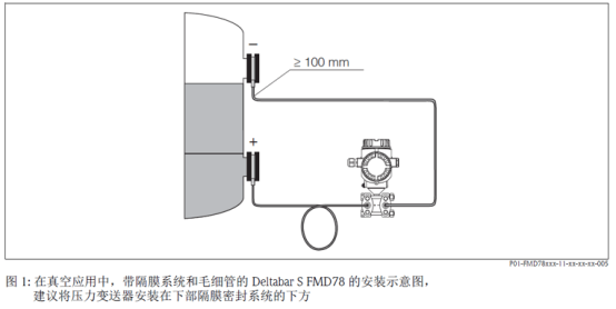
5. FMD78 Capillary Installation Key Points
When installing the capillary of the FMD78, in order to obtain more accurate measurement results and avoid instrument failure, note the following:
- No vibration (to avoid additional pressure fluctuations).
- Do not install near heating pipes or cooling pipes.
- When the ambient temperature is lower or higher than the reference temperature, the capillary should be insulated (bending radius: 100 mm).
- When using a double-sided diaphragm seal system, the ambient temperature and length of the two capillaries should be the same.
- Identical double-sided diaphragms (e.g., flange diaphragm diameter, material, etc.) should always be connected to the negative pressure side and positive pressure side (standard factory setting).
6. Electrical Wiring
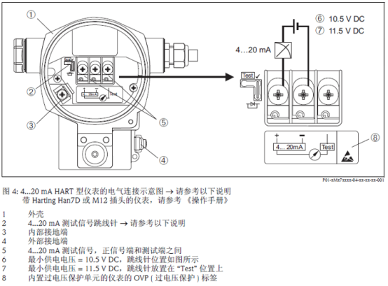
Correct wiring is the foundation for the normal operation of the instrument. Please refer to the following wiring diagram and cable specifications.
Wiring Diagram
Cable Specifications
- Shielded, two-core twisted-pair cable is recommended.
- Wire core cross-sectional area of the terminal: 0...2.5 mm².
- Cable outer diameter: ...9 mm.