
PMX7x/FMX7x Brief Operating Instructions
1 Pressure Measurement
1.1 Calibration under Reference Pressure
Example:
A 500 mbar pressure gauge needs to be set to a range of 0 to 300 mbar, so 0 and 300 mbar should correspond to 4 and 20 mA respectively.
Prerequisites:
The instrument has been installed and can be pressurized to 0 mbar and 300 mbar.
Steps:
1. Before setting parameters, ensure the impulse line is clear and filled with filling liquid. 2. Perform zero point correction if necessary.
3. Select pressure measurement mode in the measurement mode. Menu path: GROUP SELECTION → MEASURING MODE
4. Select the basic setup menu.
Menu path: GROUP SELECTION → OPERATING
MENU → SETTINGS → BASIC SETUP
5. In the pressure unit PRESS. ENG. UNIT menu, select the desired pressure unit; here select mbar.
6. At this time, the value measured by the instrument is 0 mbar, which is the zero scale corresponding to 4 mA. Select GET LRV to confirm the current value. The currently measured pressure value will be set as the zero point value (4 mA).
7. Pressurize to 300 mbar. Select GET URV to confirm the current value. The currently measured pressure value will be set as the full scale value (20 mA).
8. Complete. The instrument range is now set to 0 to 300 mbar.
Example:
A 400 mbar pressure gauge needs to be set to a range of 0 to 300 mbar, so 0 and 300 mbar should correspond to 4 and 20 mA respectively.
Prerequisites:
This is a theoretical calibration; only the pressure values corresponding to 4 and 20 mA need to be known.
Steps:
1. Select pressure measurement mode in the measurement mode. Menu path: GROUP SELECTION → MEASURING MODE
2. Select the basic setup menu.
Menu path: GROUP SELECTION → OPERATING
MENU → SETTINGS → BASIC SETUP
3. In the pressure unit PRESS. ENG. UNIT menu, select the desired pressure unit; here select mbar.
4. Select SET LRV. Enter the zero scale value corresponding to 4 mA.
5. Select SET URV. Enter the full scale value corresponding to 20 mA.
6. Complete. The instrument range is now set to 0 to 300 mbar.
2 Level Measurement
2.1 Phase
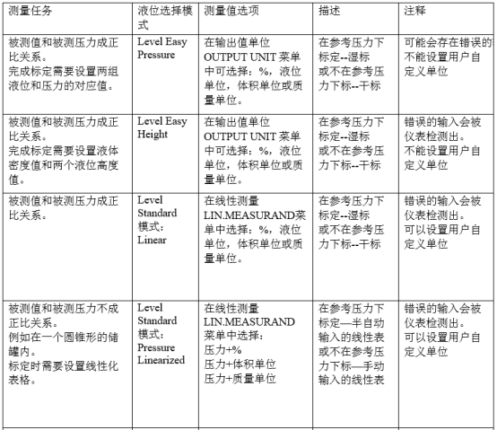
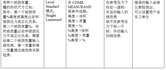
2.2 Level Easy Pressure
2.2.1 Calibration under Reference Pressure - Wet Calibration
Example:
The level in a tank needs to be measured in m. The maximum level is 3 m. The pressure setting range is 0 to 300 mbar.
Prerequisites:
The measured variable is proportional to pressure.
The tank needs to be filled or emptied.
Steps:
1. Before setting parameters, ensure the impulse line is clear and filled with filling liquid.
2. Perform zero point correction if necessary.
3. Select level measurement mode in the measurement mode.
Menu path: GROUP SELECTION → MEASURING MODE
4. In the level selection LEVEL SELECTION mode, select the level corresponding to pressure Level Easy Pressure mode.
5. Select the basic setup menu.
Menu path: GROUP SELECTION → OPERATING
MENU → SETTINGS → BASIC SETUP
6. In the output unit OUTPUT UNIT menu, select the desired level unit; here select m.
7. In the calibration mode CALIBRATION MODE, select wet calibration.
8. Empty the tank and measure the static pressure corresponding to the zero point. At this time, the value measured by the instrument is 0 mbar.
Select the empty calibration EMPTY CALIB. menu and enter the level value; here it is 0 m. Confirm that the current pressure value has been set.
9. Fill the tank and measure the static pressure corresponding to the full scale. At this time, the value measured by the instrument is 300 mbar. Select the full calibration FULL CALIB. menu and enter the level value; here it is 3 m. Confirm that the current pressure value has been set.
10. Select SET LRV. Enter the zero scale value corresponding to 4 mA.
11. Select SET URV. Enter the full scale value corresponding to 20 mA.
12. Complete. The instrument range is now set to 0 to 3 m.
2.2.2 Calibration not under Reference Pressure - Dry Calibration
Example:
This time, use liters as the unit to measure the volume in the tank. The maximum value 1000 liters corresponds to a pressure of 450 mbar. The minimum value 0 liters corresponds to a pressure of 50 mbar. The instrument is installed below the zero level.
Prerequisites:
The measured variable is proportional to pressure.
The pressure and volume values for zero and full scale must be known.
Steps:
1. Select level measurement mode in the measurement mode.
Menu path: GROUP SELECTION → MEASURING MODE
2. In the level selection LEVEL SELECTION mode, select the level corresponding to pressure Level Easy Pressure mode.
3. Select the basic setup menu.
Menu path: GROUP SELECTION → OPERATING
∪ → SETTINGS → BASIC SETUP
4. In the pressure unit PRESS. ENG. UNIT menu, select the desired pressure unit; here select mbar.
5. In the output unit OUTPUT UNIT menu, select the desired level unit; here select liters L.
6. In the calibration mode CALIBRATION MODE, select dry calibration DRY. In the empty calibration EMPTY CALIB. menu, enter the volume value corresponding to the zero level; here it is 0 L. In the empty pressure EMPTY PRESSURE menu, enter the pressure value corresponding to the zero level; here it is 50 mbar. In the full calibration FULL CALIB. menu, enter the volume value corresponding to the full scale level; here it is 1000 L.
10. In the full pressure FULL PRESSURE menu, enter the pressure value corresponding to the full scale level; here it is 450 mbar.
11. Select SET LRV. Enter the zero scale value corresponding to 4 mA.
12. Select SET URV. Enter the full scale value corresponding to 20 mA.
13. Complete. The instrument range is now set to 0 to 1000 L.
2.3 Level Easy Height
2.3.1 Calibration under Reference Pressure - Wet Calibration
Example:
This time, use liters as the unit to measure the volume in the tank. The maximum capacity 1000 L corresponds to a level of 4.5 m. The minimum capacity 0 L corresponds to a level of 0.5 m.
The instrument is installed below the lowest level.
Prerequisites:
The measured variable is proportional to pressure.
The tank can be filled and emptied.
1. Before setting parameters, ensure the impulse line is clear and filled with filling liquid.
2. Perform zero point correction if necessary.
3. Select level measurement mode in the measurement mode.
Menu path: GROUP SELECTION → MEASURING MODE
4. In the level selection LEVEL SELECTION mode, select the level corresponding to pressure Level Easy Pressure mode.
5. Select the basic setup menu.
Menu path: GROUP SELECTION → OPERATING
MENU → SETTINGS → BASIC SETUP
6. In the pressure unit PRESS. ENG. UNIT menu, select the desired pressure unit; here select mbar.
7. In the output unit OUTPUT UNIT menu, select the desired volume unit; here select L.
8. In the level unit HEIGHT UNIT menu, select the desired level unit; here select m.
9. In the calibration mode CALIBRATION MODE, select wet calibration WET.
10. In the density unit DENSITY UNIT menu, select the desired density unit; here select kg/dm3.
11. In the adjust density ADJUST DENSITY menu, enter the density of the measured medium.
12. Empty the tank to the zero point, and in the empty calibration EMPTY CALIB. menu, enter the volume value; here it is 0 L. (The current actual measured pressure is displayed as a level value, e.g., 0.5 m).
13. Fill the tank to the full scale, and in the full calibration FULL CALIB. menu, enter the volume value; here it is 1000 L. (The current actual measured pressure is displayed as a level value, e.g., 4.5 m).
14. Select SET LRV. Enter the zero scale value corresponding to 4 mA.
15. Select SET URV. Enter the full scale value corresponding to 20 mA.
16. Complete. The instrument range is now set to 0 to 1000 L.
2.3.2 Calibration not under Reference Pressure - Dry Calibration
Example:
This time, use liters as the unit to measure the volume in the tank. The maximum capacity 1000 L corresponds to a level of 4 m. The density of the measured medium is 1 kg/dm3.
The instrument is installed below the lowest level.
Prerequisites:
The measured variable is proportional to pressure.
The level and volume values for zero and full scale must be known.
Steps:
1. Select level measurement mode in the measurement mode.
Menu path: GROUP SELECTION → MEASURING MODE
2. In the level selection LEVEL SELECTION mode, select the level corresponding to pressure Level Easy HEIGHT mode.
3. Select the basic setup menu.
Menu path: GROUP SELECTION → OPERATING
MENU → SETTINGS → BASIC SETUP
4. In the pressure unit PRESS. ENG. UNIT menu, select the desired pressure unit; here select mbar.
5. In the output unit OUTPUT UNIT menu, select the desired volume unit; here select liters L.
6. In the level unit HEIGHT UNIT menu, select the desired level unit; here select m.
7. In the calibration mode CALIBRATION MODE, select dry calibration DRY.
8. In the density unit DENSITY UNIT menu, select the desired density unit; here select kg/dm3.
9. In the adjust density ADJUST DENSITY menu, enter the density of the measured medium.
10. In the empty calibration EMPTY CALIB. menu, enter the volume value corresponding to the zero level; here it is 0 L.
11. In the empty height EMPTY HEIGHT menu, enter the level value corresponding to the zero level; here it is 0.5 m.
12. In the full calibration FULL CALIB. menu, enter the volume value corresponding to the full scale level; here it is 1000 L.
13. In the full height FULL HEIGHT menu, enter the level value corresponding to the full scale level; here it is 4.5 m.
14. Select SET LRV. Enter the zero scale value corresponding to 4 mA.
15. Select SET URV. Enter the full scale value corresponding to 20 mA.
16. Complete. The instrument range is now set to 0 to 1000 L.
2.4 Level Standard, Linear
2.4.1 Calibration under Reference Pressure - Wet Calibration
Example:
This time, use meters as the unit to measure the level in the tank. The maximum level is 3 m. The pressure range is from 0 to 300 mbar.
Prerequisites:
The measured variable is proportional to pressure.
The tank can be filled and emptied.
Steps:
1. Before setting parameters, ensure the impulse line is clear and filled with filling liquid.
2. Perform zero point correction if necessary.
3. Select level measurement mode in the measurement mode. Path: GROUP SELECTION → MEASURING MODE
4. In the level selection LEVEL SELECTION mode, select the level corresponding to pressure Level Standard mode.
5. Select the basic setup menu.
Menu path: GROUP SELECTION → OPERATING
MENU → SETTINGS → BASIC SETUP
6. In the pressure unit PRESS. ENG. UNIT menu, select the desired pressure unit; here select mbar.
7. In the level mode LEVEL MODE menu, select the linear Linear option.
8. In the measured linear variable Lin. MEASURAND menu, select the level Level option.
9. In the level unit HEIGHT UNIT menu, select the desired level unit; here select m.
10. In the calibration mode CALIBRATION MODE, select wet calibration Wet.
11. Empty the tank pressure to the zero point; here it is 50 mbar. In the empty calibration EMPTY CALIB. menu, enter the level value; here it is 0 m. Confirm that the level value corresponding to the minimum pressure value entered at this time is the zero point.
12. Fill the tank pressure to the full scale; here it is 450 mbar. In the full calibration FULL CALIB. menu, enter the level value; here it is 3 m. Confirm that the level value corresponding to the maximum pressure value entered at this time is the full point.
13. Select SET LRV. Enter the zero scale value corresponding to 4 mA.
14. Select SET URV. Enter the full scale value corresponding to 20 mA.
Complete. The instrument range is now set to 0 to 3 m.
2.4.2 Calibration not under Reference Pressure - Dry Calibration
Example:
This time, use m3 as the unit to measure the volume in the tank. The maximum capacity 5 m3 corresponds to the highest level 4 m. The density of the measured medium is 1 kg/dm3.
The instrument is installed below the lowest level.
Prerequisites:
The measured variable is proportional to pressure. The tank volume, tank height, and density of the measured medium must be known.
Steps:
1. Select level measurement mode in the measurement mode.
Menu path: GROUP SELECTION → MEASURING
MODE
2. In the level selection LEVEL SELECTION mode, select the level corresponding to pressure Level Standard mode.
3. Select the basic setup menu.
Menu path: GROUP SELECTION → OPERATING
MENU → SETTINGS → BASIC SETUP
4. In the pressure unit PRESS. ENG. UNIT menu, select the desired pressure unit; here select mbar.
5. In the level mode LEVEL MODE menu, select the linear option.
6. In the measured linear variable Lin. MEASURAND menu, select the volume Volume option.
7. In the volume unit VOLUME UNIT menu, select the desired volume unit; here select m3.
8. In the calibration mode CALIBRATION MODE, select dry calibration DRY.
9. In the density unit DENSITY UNIT menu, select the desired density unit; here select kg/dm3.
10. In the adjust density ADJUST DENSITY menu, enter the density of the measured medium. Here it is 1 kg/dm3.
11. In the tank volume TANK VOLUME menu, enter the tank volume value; here enter 5 m3.
12. In the tank height TANK HEIGHT menu, enter the tank height; here enter 4 m.
13. In the zero position ZERO POSITION menu, enter the level offset; here it is -0.5 m.
14. Select SET LRV. Enter the zero scale value corresponding to 4 mA.
15. Select SET URV. Enter the full scale value corresponding to 20 mA.
16. Complete. The instrument range is now set to 0 to 5 m3.
2.5 Level Standard, Pressure Linearized
2.5.1 Semi-automatic Input of Linearization Table
Example:
Measure the volume of a conical tank in m3.
Prerequisites:
The tank can be filled continuously and linearly.
Steps:
1. Before setting parameters, ensure the impulse line is clear and filled with filling liquid.
2. Perform zero point correction if necessary.
3. Select level measurement mode in the measurement mode.
Menu path: GROUP SELECTION → MEASURING MODE
4. In the level selection LEVEL SELECTION mode, select the level corresponding to pressure Level Standard mode.
5. Select the basic setup menu.
Menu path: GROUP SELECTION → OPERATING
MENU → SETTINGS → BASIC SETUP
6. In the pressure unit PRESS. ENG. UNIT menu, select the desired pressure unit; here select mbar.
7. In the level mode LEVEL MODE menu, select the pressure linearized Pressure Linearized option.
8. In the measured linear variable Lin. MEASURAND menu, select the volume Volume option.
9. In the volume unit VOLUME UNIT menu, select the desired volume unit; here select m3.
10. In the minimum hydrostatic pressure HYDR. PRESS. MIN. menu, enter the required minimum hydrostatic pressure value; here enter 0 mbar.
11. In the maximum hydrostatic pressure HYDR. PRESS. MAX. menu, enter the required maximum hydrostatic pressure value.
12. Enter the linearization menu. Menu path: GROUP SELECTION → OPERATING MENU → SETTINGS → LINEARISATION
13. In the tank minimum capacity TANK CONTENT MIN. menu, enter the specified minimum value; here enter 0 m3.
14. In the tank maximum capacity TANK CONTENT MAX. menu, enter the specified maximum value; here enter 3.5 m3.
15. In the linearization table TABLE SELECTION menu, select the edit linearization table Editor table option.
16. In the linearization edit mode LIN. TABLE MODE menu, select the semi-automatic Semiautomatic option. In the edit linearization table EDITOR TABLE menu, select the new linearization table New table option.
17. In the edit linearization table EDITOR TABLE menu, select the new linearization table New table option.
18. Enter the linearization table.
Fill the tank level to the first calibration point.
Calibration point number LINE NUM.: Confirm the calibration point number in the currently entered linearization table.
X-axis X-VAL: Display the currently measured hydrostatic pressure value.
Y-axis Y-VAL: Enter the corresponding volume value; here enter 0 m3.
19. If you want to enter the next value in the linearization table, select the next point NEXT POINT option, enter the calibration point number, and repeat step 18. If the linearization table input is complete, select the accept input table Accept input table option.
20. Linearization table complete.
2.5.2 Manual Input of Linearization Table
Example:
Measure the volume of a conical tank in m3.
Prerequisites:
The linearization table is known.
Steps:
1. Basic setup is consistent with steps 2 to 10 of 2.3.1.
2. Enter the linearization menu. Menu path: GROUP SELECTION → OPERATING
∪ → SETTINGS → LINEARISATION
3. In the tank minimum capacity TANK CONTENT MIN. menu, enter the specified minimum value; here enter 0 m3.
4. In the tank maximum capacity TANK CONTENT MAX. menu, enter the specified maximum value; here enter 3.5 m3.
5. In the linearization table selection TABLE SELECTION menu, select the edit linearization table Editor Table option.
6. In the linearization edit mode LIN. TABLE MODE menu, select the manual Manual option.
7. In the edit linearization table EDITOR TABLE menu, select the new linearization table New table option.
8. Enter the linearization table (minimum 2 points, maximum 32 points).
Calibration point number LINE NUM.: Confirm the calibration point number in the currently entered linearization table.
X-axis X-VAL: Enter the pressure value and confirm.
Y-axis Y-VAL: Enter the corresponding volume value and confirm; here enter 0 m3.
9. If you want to enter the next value in the linearization table, select the next point NEXT POINT option, enter the calibration point number, and repeat step 18.
If the linearization table input is complete, select the accept input table Accept input table option.
10. Linearization table complete.
2.6 Level Standard, Height Linearized
2.6.1 Wet Calibration and Semi-automatic Input of Linearization Table
Example:
Level and volume need to be measured simultaneously.
Prerequisites:
The tank can be filled continuously and linearly.
1. Before setting parameters, ensure the impulse line is clear and filled with filling liquid.
2. Perform zero point correction if necessary.
3. Select level measurement mode in the measurement mode.
Menu path: GROUP SELECTION → MEASURING MODE
4. In the level selection LEVEL SELECTION mode, select the level corresponding to pressure Level Standard mode.
5. Select the basic setup menu.
Menu path: GROUP SELECTION → OPERATING
MENU → SETTINGS → BASIC SETUP
6. In the pressure unit PRESS. ENG. UNIT menu, select the desired pressure unit; here select mbar.
7. In the level mode LEVEL MODE menu, select the height linearized Height Linearized option.
8. In the measurement mode COMB. MEASURAND menu, select the height + volume Height + Volume option.
9. In the level unit HEIGHT UNIT menu, select the unit of the first measured variable; here select m.
10. In the volume unit UNIT VOLUME menu, select the unit of the second measured variable; here select m3.
11. In the minimum level LEVEL MIN. menu, enter the minimum level value; here enter 0 m.
12. In the maximum level LEVEL MAX. menu, enter the maximum level value; here enter 3 m.
13. In the calibration mode CALIBRATION MODE, select wet calibration Wet. (The calibration mode is used for the first measured variable.)
14. The current tank pressure value is the zero point of calibration. Here it is 0 mbar.
In the empty calibration EMPTY CALIB. menu, enter the zero level value; here enter 0 m. Confirm that the current pressure value corresponds to the zero level.
15. The current tank pressure value is the full scale point of calibration. Here it is 300 mbar.
In the full calibration FULL CALIB. menu, enter the full scale level value; here enter 3 m. Confirm that the current pressure value corresponds to the full scale level.
16. Calibration of the first measured variable is complete.
17. Enter the linearization menu. Menu path: GROUP SELECTION → OPERATING
MENU → SETTINGS → LINEARISATION
18. In the tank minimum capacity TANK CONTENT MIN. menu, enter the specified minimum value; here enter 0 m3.
19. In the tank maximum capacity TANK CONTENT MAX. menu, enter the specified maximum value; here enter 5 m3.
20. In the linearization table selection TABLE SELECTION menu, select the edit linearization table Editor Table option.
21. In the linearization edit mode LIN. TABLE MODE menu, select the semi-automatic Semiautomatic option.
22. In the edit linearization table EDITOR TABLE menu, select the new linearization table New table option.
23. Enter the linearization table.
Fill the tank level to the first calibration point.
Calibration point number LINE NUM.: Confirm the calibration point number in the currently entered linearization table.
X-axis X-VAL: Display the level value corresponding to the currently measured hydrostatic pressure value.
Y-axis Y-VAL: Enter the corresponding volume value; here enter 0 m3.
24. If you want to enter the next value in the linearization table, select the next point NEXT POINT option, enter the calibration point number, and repeat step 18.
If the linearization table input is complete, select the accept input table Accept input table option.
25. Linearization table input complete.
2.6.2 Dry Calibration and Manual Input of Linearization Table
Example:
Level and volume need to be measured simultaneously.
Conditions:
They are known.
Steps:
1. Complete calibration consistent with steps 3 to 12 of 2.4.1.
2. In the calibration mode CALIBRATION MODE, select dry calibration DRY.
3. In the adjust density ADJUST DENSITY menu, enter the density of the measured medium. Here it is 1 kg/dm3.
4. In the zero position ZERO POSITION menu, enter the level offset; here it is 0 m.
5. Calibration of the first measured variable is complete.
6. Enter the linearization menu. Menu path: GROUP SELECTION → OPERATING
MENU → SETTINGS → LINEARISATION
7. In the tank minimum capacity TANK CONTENT MIN. menu, enter the specified minimum value; here enter 0 m3.
8. In the tank maximum capacity TANK CONTENT MAX. menu, enter the specified maximum value; here enter 5 m3.
9. In the linearization table selection TABLE SELECTION menu, select the edit linearization table Editor Table option.
10. In the linearization edit mode LIN. TABLE MODE menu, select the manual Manual option.
11. In the edit linearization table EDITOR TABLE menu, select the new linearization table New table option.
12. Enter the linearization table.
Fill the tank level to the first calibration point.
Calibration point number LINE NUM.: Confirm the calibration point number in the currently entered linearization table.
X-axis X-VAL: Enter the level value and confirm.
Y-axis Y-VAL: Enter the corresponding volume value; here enter 0 m3 and confirm.
13. If you want to enter the next value in the linearization table, select the next point NEXT POINT option, enter the calibration point number, and repeat step 18. If the linearization table input is complete, select the accept input table Accept input table option.
14. Linearization table input complete.
3 Flow Measurement
3.1 Calibration
Example:
Measure volume flow in m3/s.
Note:
Only the differential pressure transmitter Deltabar S has a flow measurement mode.
Steps:
1. Before setting parameters, ensure the impulse line is clear and filled with filling liquid.
2. Perform zero point correction if necessary.
3. Select flow measurement mode in the measurement mode.
Menu path: GROUP SELECTION → MEASURING MODE
4. Select the basic setup menu.
Menu path: GROUP SELECTION → OPERATING
MENU → SETTINGS → BASIC SETUP
5. In the pressure unit PRESS. ENG. UNIT menu, select the desired pressure unit; here select mbar.
6. In the flow measurement type FLOW-MEAS. TYPE menu, select the volume flow Volume p. cond. mode.
7. In the flow unit UNIT FLOW menu, select the desired flow unit; here select m3/h.
8. In the maximum flow MAX. FLOW menu, enter the maximum flow value, e.g., here enter 6000 m3/h; this value needs to refer to the planning document. In the maximum pressure value corresponding to maximum flow MAX. PRESS. FLOW menu, enter the maximum pressure value, e.g., here enter the corresponding 400 mbar; this value needs to refer to the planning document.
9. Complete. The range is now set to 0 to 6000 m3/h.
3.2 Totalizers
Example:
The volume flow needs to be accumulated in m3, and negative flow also needs to be accumulated.
Note:
Totalizer 1 can be reset, Totalizer 2 cannot be reset.
Steps:
1. Complete calibration consistent with steps of 6.1.
2. Select the totalizer setup menu.
Menu path: GROUP SELECTION → OPERATING
MENU → SETTINGS → TOTALIZER SETUP
3. In the totalizer 1 unit TOTALIZER 1 UNIT menu, set the accumulated flow unit; here select m3.
4. In the negative flow totalizer 1 NEG. FLOW TOT. 1 menu, select the desired accumulation mode; here select Inc. On Neg. Flow mode.
5. In the reset totalizer RESET TOTALIZER menu, reset totalizer 1.
6. The accumulated flow 1 TOTALIZER 1 and accumulated flow overflow value 1 TOTAL. 1 OVERFLOW menus start displaying the accumulated flow value.