
FMR50 Radar Level Transmitter Installation Precautions
Correct installation is the foundation for ensuring the measurement accuracy of the FMR50 radar level transmitter. The following explains three aspects: installation location, installation method, and mechanical adjustment.
Installation Location and Environmental Requirements
- Avoid interference within the beam angle: Ensure there are no interfering objects such as baffles or heating coils within the beam range (beam angle α: 23° for 40mm antenna, 10° for 80mm, 8° for 100mm).
- Special requirements for plastic containers: For non-metallic tanks (such as GRP), ensure there are no metal pipes/ladders outside the beam range; otherwise, installation is prohibited.
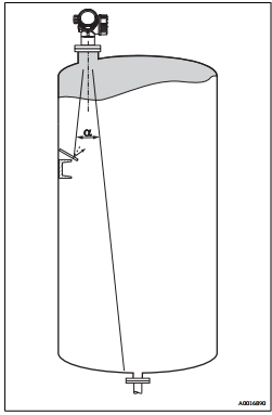
Installation Method and Structure
- Stilling well installation:
- The pipe diameter must be uniform, the inner wall smooth (surface roughness ≤6.3μm), and welds precisely aligned.
- The guide slot angle must be 180° (not 90°), with gaps ≤1mm.
- Bypass pipe installation: The pipe diameter must match the antenna size; accuracy may decrease within ±20cm of the tank connection.
- Tanks with insulation layers: The insulation layer thickness must not exceed the device neck to avoid overheating of electronic components (Document 6.6).
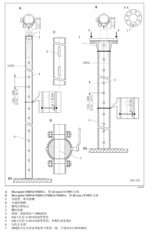
Mechanical Adjustment
- Rotating the transmitter housing: Use a wrench to loosen the screw and then rotate the housing (maximum torque: 1.5Nm for plastic, 2.5Nm for metal) for easier operation.
- Rotating the display unit: Pull out the display module and rotate to the desired angle (8×45°), ensuring the cable is embedded in the housing gap.
FMR50 Radar Level Transmitter Wiring Precautions
Correct wiring directly affects the safe and stable operation of the instrument, and electrical specifications must be strictly followed.
Electrical Safety Specifications
- Grounding requirements:
- Protective grounding (PE) must be connected to the power supply, and the external grounding terminal must be connected to the plant grounding system.
- Warning: Do not disconnect the grounding connection before disconnecting the power supply.
- Explosion-proof areas: Must comply with the Safety Guide (XA); overvoltage protection units must be certified to DIN EN 60079-14.
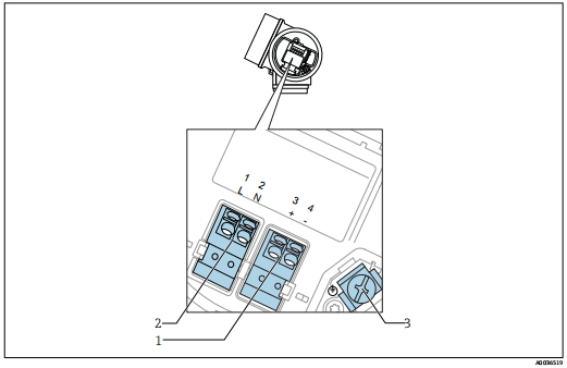
Wiring Operation Steps
- Terminal assignment: FOUNDATION Fieldbus: terminals 1-2 for power supply, 3-4 for signal; the shield must be connected to the dedicated grounding terminal (Document 7.2.2).
- Cable specifications: Cross-sectional area 0.5-2.5mm² (20-14AWG); in high-temperature environments (≥60℃), temperature resistance (TU+20K) is required.
- Opening the terminal compartment cover: Use a hex wrench to turn the fixing clip counterclockwise, and check the integrity of the sealing ring.
Instrument Plugs and Interfaces
- M12/7/8° plugs: Pin assignment must strictly follow the documentation to avoid polarity errors.
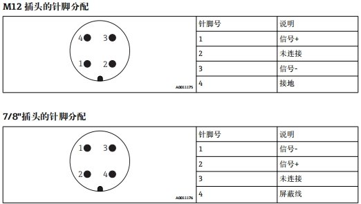
Safety and Certification Requirements
- Installation in hazardous areas: Check the explosion-proof certification on the nameplate (such as ATEX, IECEx) and strictly follow the Safety Guide.
- Overvoltage protection: For flammable liquid measurement, an internal or external OVP unit (such as HAW562/569) must be used; selection code NA.
Key Post-Installation Checks
- Mechanical integrity: Confirm flange/thread tightening (torque: 35Nm for threaded connections) and no damage to sealing rings.
- Electrical verification: Measure whether the supply voltage matches the nameplate (9-32V DC); grounding resistance ≤1Ω.
- Functional test: After power-on, check whether the display unit works normally and record the reference curve for diagnostics.
Important note: Before operation, be sure to read Chapter 2 of the documentation, "Basic Safety Guide," which involves legal liability clauses such as personnel qualifications and explosion-proof requirements. Through the above structured points, installation and wiring risks can be systematically avoided to ensure reliable operation of the FMR50.