
Overview of Process Connections and Sealing Faces
In E+H instrument selection, the process connection is a key link to ensure reliable docking between the instrument and the pipeline or equipment. Common connection methods mainly include two major categories: flange connection and threaded connection. Flange connections are suitable for medium- and high-pressure, large-diameter scenarios; threaded connections are suitable for low-pressure, small-diameter scenarios. Correctly selecting the connection standard and specifications directly affects sealing performance, installation efficiency, and system safety.
Analysis of Core Flange Standards
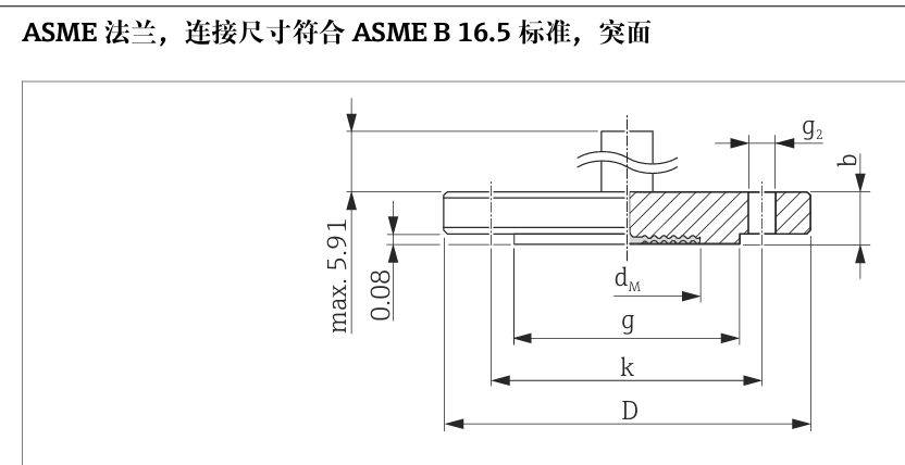
ASME B16.5 American Standard Flanges
ASME B16.5 is the pipe flange standard formulated by the American Society of Mechanical Engineers, widely used in the North American market and global inch-based systems. Its specifications usually include nominal diameter, pressure rating, sealing face type, and material.
- Pressure Class: Represents the maximum working pressure at the reference temperature, such as Class 150, 300, 2500, etc.
- Nominal Pipe Size (NPS): The nominal diameter of the inch-based piping system, not the actual outer diameter, directly determines the connection dimensions.
- Sealing Face Type: RF (raised face) is the most common; FF (flat face) is suitable for low-pressure flammable and explosive conditions; RTJ (ring joint) is suitable for high pressure and high temperature.
For example: ASME B16.5, NPS 2, Class 300, RF, 316L SS indicates a nominal diameter of 2 inches, pressure class 300, raised face seal, and 316L stainless steel material.
EN 1092-1 European Standard Flanges
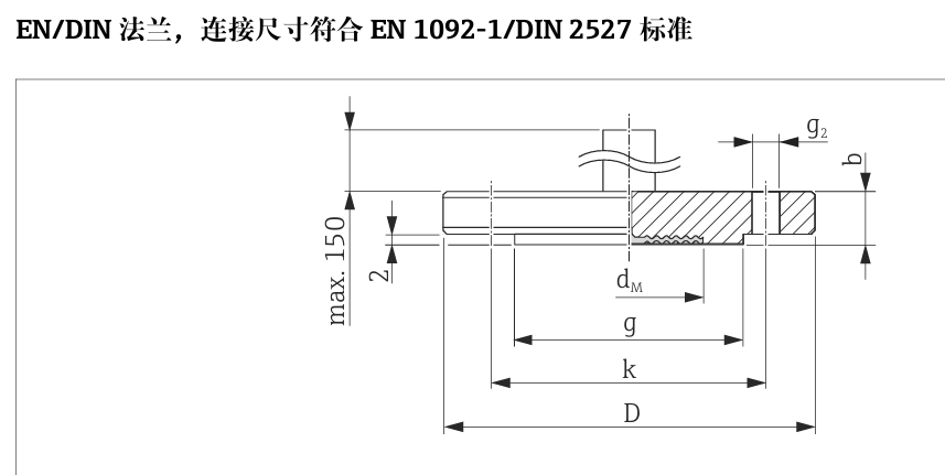
EN 1092-1 is the flange standard formulated by the European Union, applicable to Europe and scenarios adopting the European standard system. Its flange types are rich, and common ones include:
- Type A: Plate flat welding flange, sealing face is FF, suitable for low-pressure and normal-temperature working conditions.
- Type B1/B2: Hubbed slip-on/welding neck flange, sealing face is RF, B2 has a thicker hub and slightly higher pressure resistance.
- Type C/D/E/F: Correspond to special connection methods such as socket welding, threaded, and large diameter, respectively.
HG/T National Standard Flanges
HG/T 20592 is equivalent to the EN standard, suitable for domestic European standard design projects; HG/T 20615 is equivalent to ASME B16.5, suitable for domestic American standard design projects. Both sealing faces are RF raised face, and can be used with European standard and American standard gaskets respectively.
Other Regional Standards
- JIS B2220: Japanese standard flange, pressure ratings 10K/20K/30K, suitable for connecting Japanese-funded equipment.
- AS4087 / AS2129 Table E: Australian standard flanges.
Analysis of Core Thread Standards
ASME B1.20.1 American Standard Threads
This standard covers NPT tapered pipe threads and NPSM straight pipe threads, and is the most commonly used thread standard in North America and inch-based systems.
- NPT Thread: 60° tapered pipe thread, taper 1:16, sealing achieved by metal-to-metal compression, suitable for small-diameter low-pressure pipelines.
- NPSM Thread: 60° straight pipe mechanical thread, which itself does not have sealing capability and needs to be used with a gasket.
ISO 228 British Standard Threads
The G thread specified in ISO 228 is a non-sealing cylindrical pipe thread with a thread angle of 55°, which relies on gaskets or sealant for sealing, suitable for low-pressure scenarios in Europe and parts of Asia.
DIN 13 German Standard Threads
DIN 13 is the metric general-purpose thread standard formulated by the German Institute for Standardization, with a thread angle of 60°, straight cylindrical type, marked by nominal diameter × pitch (e.g., M12×1.5). It is divided into coarse and fine threads, and fine threads have better sealing performance.
Special Functional Components and Connections
Isolators and Separators
- Isolator: Used to isolate corrosive and viscous media from the instrument sensor, such as diaphragm seal isolators.
- Separator: Used to filter impurities in fluids or separate gas-liquid two phases, such as gas-liquid separators and oil-water separators.
Adapters and Extension Flanges
- Adapter: Used to convert interface types, such as NPT1/4 to UNF7/16.
- Extension Flange: The flange body is lengthened, used in scenarios where there is a distance difference between the equipment interface and the pipeline, divided into European standard B1 type and American standard RF type.
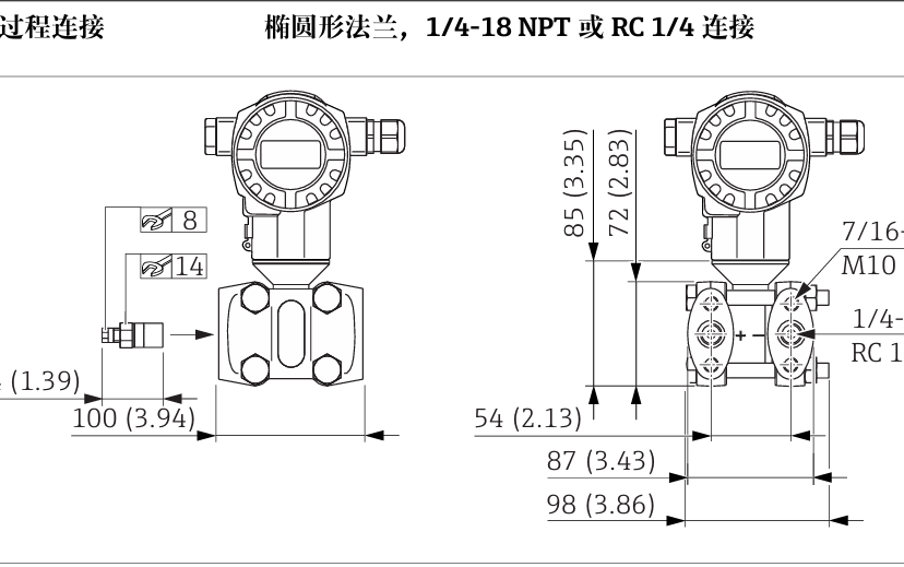
Clamped Diaphragm Seals and Diaphragm Connections
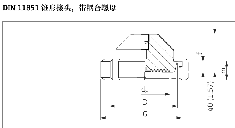
The clamped diaphragm seal clamps the diaphragm seal between the equipment and the pipeline via bolts, suitable for scenarios where the diaphragm seal needs to be replaced frequently. The diaphragm connection integrates a diaphragm sealing structure at the interface, which can prevent medium leakage or contamination, suitable for corrosive, high-viscosity, or sanitary media.
Selection Key: Standard Matching
Connection components of different standards cannot be directly interchanged. During selection, the following three points must be confirmed:
- Regional Standard: Choose ASME/NPT for North America, and EN/ISO228(G)/DIN13 for Europe/domestic.
- Size Specification: For flanges, look at "nominal diameter + pressure rating"; for threads, look at "specification".
- Sealing Requirement: Choose tapered pipe thread (NPT) for high pressure, cylindrical thread (G) + gasket for low pressure, and RF raised face + suitable gasket for flanges.
Detailed Explanation of Process Connection Parameters
Inch-Based Flange Specifications
Specification format: Code + NPS + Cl. + Material + Extension Length (optional). For example: NPS 1-1/2, Cl.300, 316/316L, extension length 2". Among them, NPS is the inch-based nominal diameter, Cl. is the pressure rating, 316/316L is the corrosion-resistant material, and the extension length is used for distance difference scenarios.
Metric Flange Specifications
Specification format: Code + DN + PN + Material + Extension Length (optional). For example: DN25, PN10-40, 316L, extension length 50mm. DN is the metric nominal diameter, PN is the pressure rating, 316L is low-carbon stainless steel, and the extension length adapts to the European standard system.
Threaded Interface Specifications
Specification format: Code + Thread Type + Installation Method + Material + Hole Diameter (optional). For example: G1/2, flush mounting, 316L, hole diameter 11.4mm. G1/2 is an ISO228 non-sealing cylindrical pipe thread, which relies on end-face gasket sealing.
Special Sealed Components
Specification format: Code + Structure Type + Size/Pressure + Material + Sealing Method. For example: clamped diaphragm seal, diaphragm type, hole 11.4mm, separator, RC1/4 connection. The clamped diaphragm seal is clamped by bolts, and the diaphragm type has a built-in 316L stainless steel diaphragm to block medium contact.
Quick Reference Table of Key Parameters
| Parameter Type | Example | Description |
|---|---|---|
| Thread Specification | NPT1/4-18 | American tapered pipe thread, nominal 1/4 inch, 18 threads per inch |
| Thread Specification | UNF7/16-20 | American unified fine thread, outer diameter 7/16 inch, 20 threads per inch |
| Thread Specification | RC1/4" | British tapered pipe thread, nominal 1/4 inch |
| Pressure Standard | IEC61518 | Mating dimensions for differential pressure measuring instruments and flange shut-off devices |
| Pressure Rating | PN160 = M10 | Nominal pressure 16MPa, matching bolt M10 |
| Pressure Rating | PN420 = M12 | Nominal pressure 42MPa, matching bolt M12 |
| Fluid Control | 2x vent/drain valves | 2 small valves used for venting or draining |
| Fluid Control | sv = side venting | The opening direction of the vent/drain valve is on the side of the equipment |
| Fixed Connection | 4x fixing screws | 4 screws used to fix the equipment |
| Fixed Connection | Blind flange LP | Flange for closing pipeline/equipment interface, low pressure |
| Special Adaptation | Suitable for diaphragm seal installation | Compatible with diaphragm seals, isolating corrosive/high-viscosity media |
| Special Adaptation | Excluding fixing screws/vent valves | The equipment does not include these components by default |
Summary
E+H instrument process connection selection must strictly follow the standard matching principle: confirm the regional standard, size specification, and sealing requirement. For flange connections, focus on nominal diameter, pressure rating, and sealing face type; for threaded connections, focus on thread standard and sealing method. Under special working conditions, components such as extension flanges, adapters, isolators, or diaphragm seals can be selected. Correct selection can ensure long-term stable operation of the instrument and reduce the risk of leakage.