
RSG35 Data Logger Wiring Overview
The RSG35 universal data logger is used for electronic reading, display, recording, analysis, remote transmission, and backup of analog and digital input signals. The device can be designed for panel or cabinet mounting, and can also optionally be operated on a desktop or in a field enclosure. The following introduces its line connections and basic setup methods.
Detailed RSG35 Wiring Steps
Taking the connection between the temperature transmitter TM82 and the RSG35 as an example, proceed according to the wiring diagram on the RSG35. The specific wiring steps are as follows:
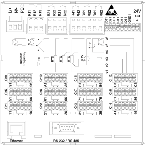
- Connect the 24V power supply: Connect the 24V power line to the RSG35 power terminals, where L is positive and N is negative.
- Connect the transmitter positive pole: Connect the transmitter positive pole to the positive pole of the auxiliary terminal.
- Connect the transmitter negative pole: Connect the auxiliary terminal negative pole to the analog input terminal (either Ch1 or Ch2 is acceptable), and at the same time connect the auxiliary terminal negative pole to the 6th interface, and connect the temperature transmitter negative pole to the 5th interface.
- Other transmitters: Other types of transmitters can also be wired by referring to this connection method.
After the wiring is correct, the device can be operated and set up.
Thermocouple Wiring Methods
If connecting a thermocouple, select the corresponding terminals according to the wire configuration:
| Thermocouple Type | Wiring Terminals |
|---|---|
| Two-wire | Connect to ports 1 and 6 |
| Three-wire | Connect to terminals 1, 4, and 6 |
Please ensure the wiring is secure to avoid signal interference.