

Many users, after purchasing an electromagnetic flowmeter, have a question during use: why does the electromagnetic flowmeter still have a reading when no liquid is passing through the pipe? In fact, this is a very normal phenomenon, and it is closely related to the measurement principle of the electromagnetic flowmeter. Below we will introduce the principle of the electromagnetic flowmeter.
According to Faraday's law of electromagnetic induction, when a conductor moves in a magnetic field, an induced voltage is generated. In the electromagnetic measurement principle, the flowing medium is equivalent to a moving conductor. The induced voltage is proportional to the medium flow velocity and is applied to the amplifier through two measuring electrodes. The volumetric flow rate is calculated based on the cross-sectional area of the pipe. A switched DC current with alternating polarity generates a direct current (DC) magnetic field. Measurement is performed through the electromagnetic field. When no liquid is passing through the pipe, but the magnetic field is still present, there will still be a reading. Below is a schematic diagram of its principle.
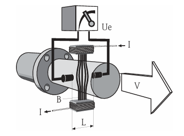
Because of the measurement principle, this cannot be avoided. When there is no liquid in the pipe, we can turn on empty pipe detection. After it is turned on, the flowmeter will output an error current when there is no liquid; if it is not turned on, it will output flow.
To turn on empty pipe detection, first enter group selection, select the measured value, then select process parameters, turn on the empty pipe detection function, enter the access password, the access password is 10, then change OFF to ON, and empty pipe detection is turned on. As shown in the figure.
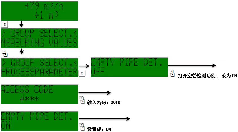
It is worth noting that when installing the device, we should install it according to the requirements in the manual.
Installation must be carried out according to the manual requirements. It is strictly prohibited to install the device at the highest point of the pipe (prone to gas accumulation) or directly above a downward-draining pipe, to prevent gas accumulation or bubbles from increasing measurement error; when installing on a horizontal pipe, the measuring electrode axis must remain horizontal to avoid bubbles causing temporary insulation between the two electrodes.
Inclined non-full pipes need to be equipped with a drain port, and the sensor must not be installed at the lowest point of an inclined pipe (to prevent solid accumulation). It is recommended to install a drain valve; the empty pipe detection function (EPD) can detect empty pipes / non-full pipes and improve safety, but it can only work normally on horizontal pipes with the transmitter head facing upward.
When installing on a vertical downward pipe with a height of ≥5 m (16.4 ft), a siphon or drain valve must be installed in the downstream pipe of the sensor to prevent suction pressure from damaging the measuring tube liner; vertical pipes are the ideal installation direction for self-draining piping systems and systems with empty pipe detection.
If used in an environment with severe vibration, the piping system and sensor need to be reinforced to avoid vibration affecting measurement stability.
The sensor installation position must be away from valves, tees, and elbow fittings, ensuring that the upstream straight pipe section length is ≥5×DN and the downstream straight pipe section length is ≥2×DN to meet measurement accuracy.
When the sensor is installed on a large-diameter pipe, an adapter pipe conforming to the DINEN545 standard (double-flange reducer) can be used. Especially when measuring fluids with extremely slow flow rates, it can increase the flow velocity and improve accuracy. Before use, refer to the diagram to calculate the system pressure loss caused by the reducer / expander.