T-mass 65 Thermal Mass Flowmeter Installation Guide
A full pipe is a prerequisite for accurate measurement with a thermal flowmeter. Therefore, please observe the following requirements when installing the flowmeter.
1. Installation Location
- Disturbed fluid conditions have a significant impact on instruments that measure based on the thermal dispersion principle. Observe the recommended upstream and downstream straight pipe length requirements.
- Rich engineering practice experience is a prerequisite for correct piping system design and installation.
- Ensure the correct installation orientation and installation position of the sensor.
- Take necessary measures to reduce or avoid condensation (e.g., install a condensate separator, provide thermal insulation, etc.).
- The requirements for the maximum permissible ambient temperature and medium temperature range must be observed.
- Install the transmitter in a shaded location, or install a protective cover.
- For mechanical reasons, to protect the pipe, it is recommended to use a mounting base when installing heavy sensors.
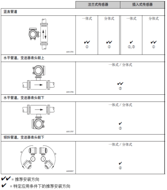
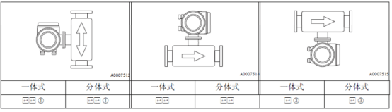
① When measuring saturated or contaminated gases, it is recommended to use a vertical pipe with upward flow to minimize the effects of condensation/contamination.
② Not recommended for use in highly vibrating environments or where installation is unstable.
③ Only suitable for clean/dry gases. If adhesion or condensation may occur, do not use a horizontal pipe with the transmitter head facing downward. Refer to the sensor installation.
④ When measuring moist gases or saturated water gases (e.g., biogas), install on an inclined pipe (a = max. 135°).
2. Insulation
When measuring moist gases or saturated water gases (e.g., steam), the pipe and flowmeter housing should be insulated to prevent water droplets from penetrating into the measuring sensor.
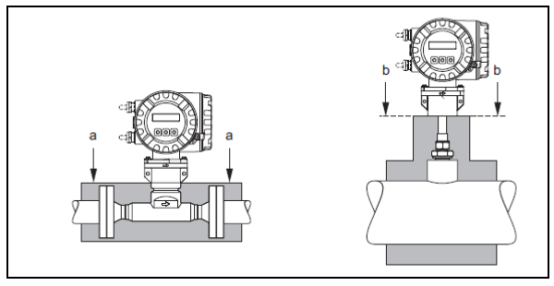
Schematic diagram of maximum insulation thickness for T-mass 65F and 65I
a. Maximum insulation thickness for flanged sensor
b. Maximum insulation thickness for insertion sensor
3. Upstream and Downstream Straight Pipe Sections for Thermal Flowmeter
Disturbed fluid conditions have a significant impact on instruments that measure based on the thermal dispersion principle. Generally, thermal flowmeters should be installed as far away as possible from disturbance sources.
For detailed information, please refer to ISO 14511.
- When two or more disturbance sources are present upstream of the flowmeter, the recommended upstream straight pipe length for the strongest disturbance source should be observed. For example: if a valve is installed before a pipe elbow, the required straight pipe length between the valve and the flowmeter should be 50 x DN. When measuring very light gases (e.g., helium and hydrogen), all upstream straight pipe lengths should be doubled.
Minimum recommended upstream and downstream straight pipe lengths (without flow conditioner):
Flanged sensor
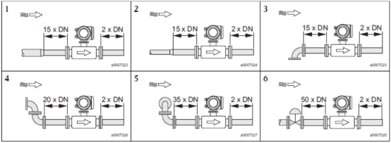
1=Reducer; 2=Expander; 3=90° elbow or T-piece; 4=2x90° elbow; 5=2x90° elbow (3-way); 6=Control valve
Insertion sensor
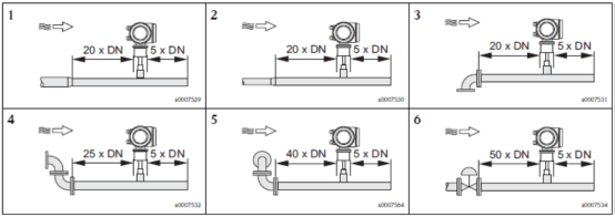
1=Reducer; 2=Expander; 3=90° elbow or T-piece; 4=2x90° elbow; 5=2x90° elbow (3-way); 6=Control valve or pressure regulator
General thermal mass flowmeter installation requirements (reducer, expander, and 90° elbow or T-piece): upstream straight pipe length flanged sensor: 15 x DN; insertion sensor: 20 x DN; downstream straight pipe length flanged sensor: 2 x DN; insertion sensor: 5 x DN.
4. Orifice Flow Conditioner
If the upstream and downstream straight pipe length requirements cannot be met, it is recommended to install an orifice flow conditioner.
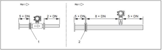
1=Flow conditioner for flanged sensor; 2=Flow conditioner for insertion sensor. The flow conditioner for insertion sensor 65I is used for pipe diameters ranging from DN 80 .. 300 mm (3...12"). The flow conditioner must be installed upstream of the sensor, with an upstream straight pipe length of 8 x DN. The flow conditioner itself also requires an upstream straight pipe length of 5 x DN. The flow conditioner for flanged sensor 65F is the t-mass F sensor specially designed by Endress+Hauser (nominal diameters DN 25 ..100 (1' ... 4")). Various mounting hole types and mounting dimensions are available, and one orifice plate can simultaneously meet the requirements of multiple different flange ratings (e.g., CI. 150 and CI.300).
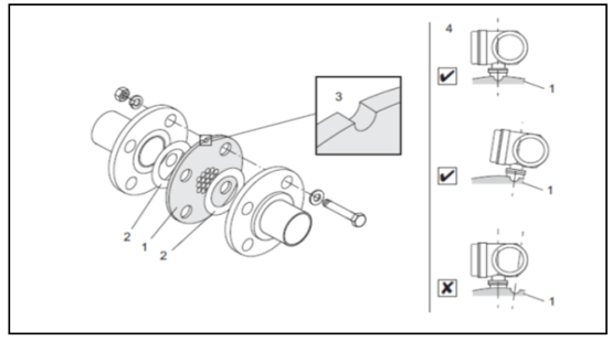
Installation of the flow conditioner:
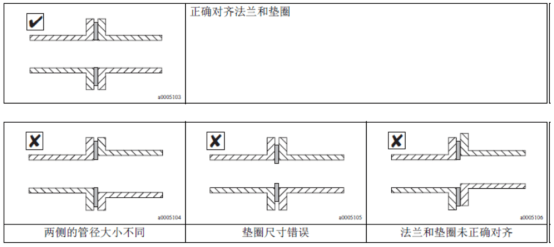
The flow conditioner and gasket must match the two pipe flanges and the flowmeter flange. Only mounting nuts that match the flange bolt holes are permitted to ensure correct positioning. The locating slot must be in the same horizontal plane as the transmitter. Incorrect installation of the flow conditioner has little effect on measurement accuracy. 1=Orifice flow conditioner; 2=Sealing ring/gasket; 3=Locating slot; 4=Calibration slot in the same plane as the transmitter
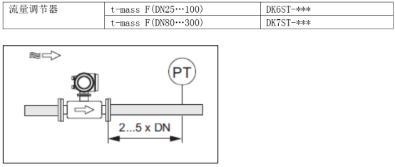
Downstream straight pipe length with pressure measurement: The measuring point should be installed on the downstream pipe of the measuring instrument to ensure that the process connection of the pressure transmitter has no effect on the flow entering the measuring point.
Note!
- To optimize measurement performance, it is recommended to order the t-mass F sensor and the flow conditioner together so that both can be calibrated simultaneously. This has very little effect on measurement performance.
- When flow conditioners from other manufacturers (not Endress+Hauser) are used with the t-mass F sensor, the fluid conditions and pressure drop in the pipe may affect measurement performance.
- Bolts, nuts, sealing rings, etc. are not standard supplied items and must be provided by the user.
5. Piping System Requirements
- The connecting pipe should have the same inner diameter as the flowmeter, and the maximum deviation in pipe diameter must not exceed:
- Diameter < DN 200 (8"): 1 mm (0.04 inch)
- Diameter ≥DN 200 (8"): 3 mm (0.12 inch)
- During reinstallation, no metal particles or abrasive particles should be generated to prevent damage to the sensing element during startup.
6. Installation Orientation of the Thermal Mass Flowmeter
Always ensure that the arrow on the sensor points in the same direction as the gas flow in the pipe.
Flanged
Insertion
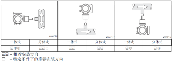
① When measuring saturated or contaminated gases, it is recommended to use a vertical pipe with upward flow to minimize the effects of condensation or contamination.
② Not recommended for use in severely vibrating environments or where installation is unstable.
③ Only suitable for measuring clean gases/dry gases. When measuring very moist gases or saturated water gases (e.g., biogas), do not install the sensor at the bottom of a horizontal pipe. An inclined pipe installation orientation should be used as shown in the figure below (a =135°).
7. Installation of the Insertion Sensor
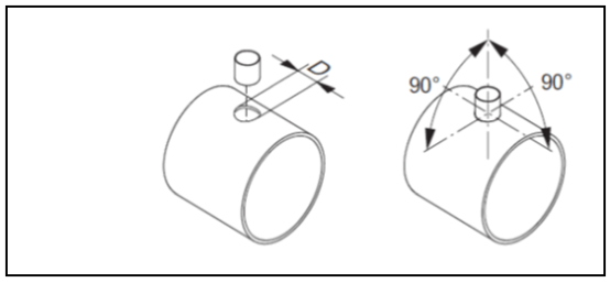
Installation conditions for the welding socket:
Caution!
When installing in thin-walled rectangular pipes, please use a suitable sensor bracket for installation.
D = Ø31.0mm±0.5 mm (Ø1.22"±0.019")
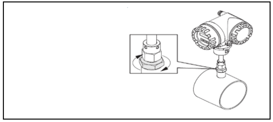
Adjusting the position of the insertion sensor:
Insert the sensor into the welding socket, hand-tighten the lower nut of the fastening sleeve, then use a wrench (42 mm) to tighten an additional 1/4 turn.
Caution!
- NPT thread: Use thread sealing tape or sealant
- G1A thread: A sealing ring must be installed (standard supplied item)
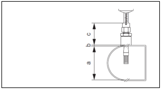
Calculation of insertion depth:
a. Inner diameter of circular pipe. When the sensor is installed vertically, the pipe height of a rectangular pipe; when the sensor is installed horizontally, the pipe width of a rectangular pipe. (a = min.80 mm or 3")
Calculate insertion depth: (0.3 x a) + b + c + 2 mm
(Insertion depth=(0.3.A)+B+(C1+C2)+0.079inch)
b. Pipe wall thickness
c. Depth of the welded stub on the pipe, including the sensor pipe connection and the online replacement mounting kit (optional).
The minimum length required for the insertion sensor can be calculated using Endress+Hauser's Applicator sizing software (version 10.02 or later) or by the following steps. The minimum length required for the insertion sensor depends on the required insertion depth. The calculated insertion depth must be within the adjustable range of the corresponding insertion sensor.
- Determine dimensions A, B, C1, and C2
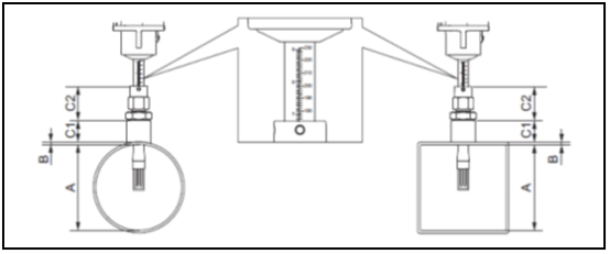
A=Circular pipe: pipe inner diameter (DN) Rectangular pipe/channel: internal dimension
B=Pipe wall thickness or channel thickness
C1+C2 =Length of mounting assembly and insertion pipe length of the fastening sleeve
Calculating the insertion depth via the sensor "Quick Setup" menu The following parameters are required when calculating the insertion depth:


- Calculate insertion depth: Insertion depth=(0.3·A)+ B + (C1 +C2)+2mm
- Compare the calculated insertion depth with the parameter values in the table below to obtain the appropriate insertion depth for the insertion sensor. The calculated insertion depth must be within the adjustable range of the corresponding insertion sensor!
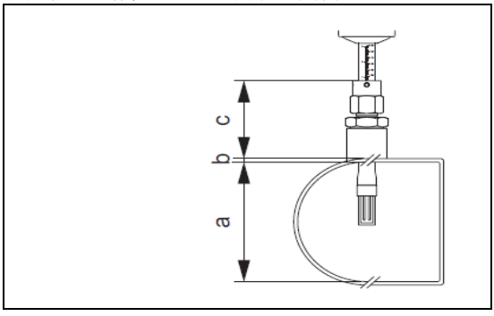
Adjusting the calculated insertion depth value:
a. Tighten the upper nut of the fastening sleeve, ensuring that sensor position adjustment is still possible.
b. Adjust the sensor position according to the calculated insertion depth value.
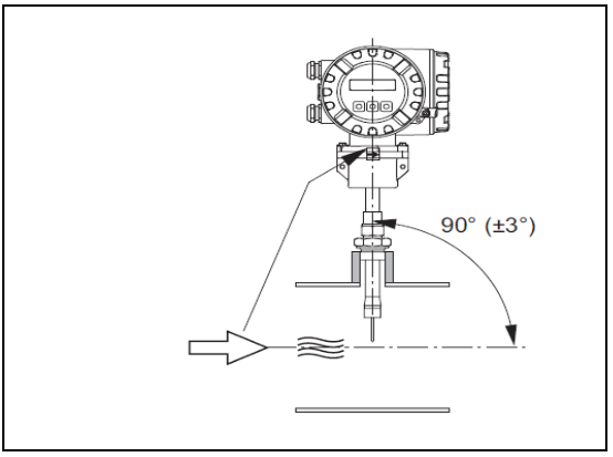
Referring to the flow direction, adjust the insertion direction of the insertion sensor. Check and confirm that the sensor installation direction on the pipe is at 90° to the flow direction, and rotate the sensor so that the arrow on the sensor points in the same direction as the flow.
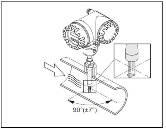
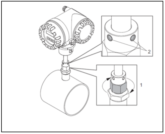
Securing the insertion sensor:
- Hand-tighten the fastening sleeve (1) to secure the sensor. Then, use an open-end wrench (36 mm) to tighten an additional 1/4 turn clockwise.
- Tighten the two fixing screws (4), (hex key 3 mm; 1/8").
Warning! Note the torque: 4 Nm (2.95 lbf ft)
- Check to ensure that the sensor and transmitter no longer rotate.
- Check the measuring point for leaks at the maximum operating pressure.
8. Transmitter Installation Guide
Rotating the field aluminum housing: Field aluminum housing, suitable for non-hazardous areas
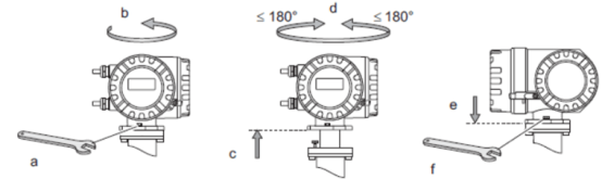
Field aluminum housing, for Zone 1 or Cl. I Div. 1 hazardous areas
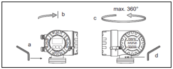
- Loosen the fixing screw.
- Gently rotate the transmitter housing clockwise until it reaches the stop position (thread top).
- Rotate the transmitter housing counterclockwise (max.360°) to the desired position.
- Retighten the fixing screw.
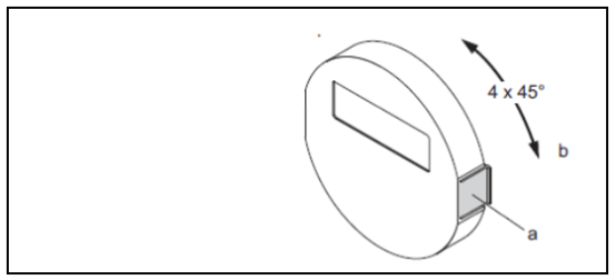
- Press the clip on the side of the display module to remove the display module from the electronics compartment cover.
- Rotate the display module to the desired position (maximum rotation angle in both directions is 4x45°), and reinstall the display module on the electronics compartment cover.