
T-mass 65 Wiring Guide: Wiring Steps and Terminal Assignment for Remote Version Mass Flowmeter
The T-mass 65 is a thermal mass flowmeter from Endress+Hauser, widely used for gas flow measurement. Correct wiring is key to ensuring measurement accuracy and equipment safety. Based on official documentation, this article systematically outlines the wiring process and terminal assignment of the T-mass 65 to help engineering technicians and procurement personnel quickly grasp the key points.
I. Checking the Nameplate
Before wiring, be sure to check the equipment nameplate information to ensure that the power supply and output type match on-site requirements. The nameplate is usually located on the side of the transmitter housing.
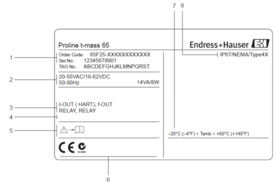
1. Order code/serial number
- Order code: uniquely identifies the device configuration, used for spare parts procurement and technical support.
- Serial number: used to trace production batch and warranty information.
2. Power supply/frequency, power consumption
- Note the distinction between 220VAC or 24VDC power supply.
- Confirm the power frequency (50/60Hz) and power consumption to ensure the power supply capacity matches.
3. Input/output configuration
- I-OUT (HART): current output, supports HART communication.
- f-OUT: frequency output.
- RELAY: relay output.
4. Operating structure and documents
The nameplate indicates the operating structure version and accompanying documents. Please refer to the corresponding manual according to the actual configuration.
5. Additional information on the device version
Includes certifications, certificates, etc., such as explosion-proof certification and CE certification, to ensure compliance with on-site safety requirements.
6. Permitted ambient temperature range
Confirm that the ambient temperature is within the permitted range to avoid measurement errors or equipment damage caused by exceeding it.
7. Degree of protection
Common degrees of protection are IP66/IP67, ensuring adaptability to the on-site environment.
II. Nameplate in the Terminal Compartment
There is also a nameplate inside the terminal compartment, providing key information such as terminal assignment and output configuration.
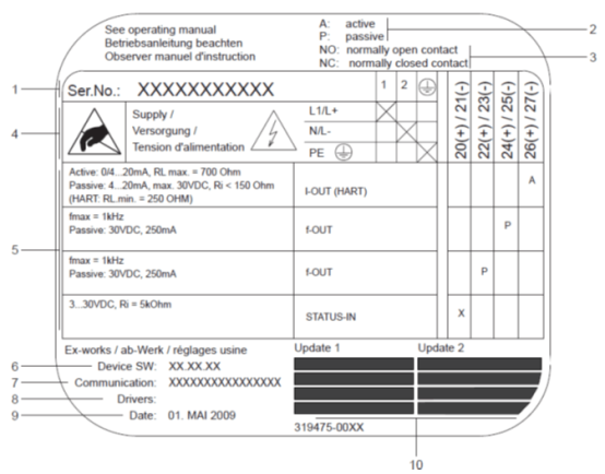
1. Serial number
Consistent with the external nameplate, used to verify the device identity.
2. Current output configuration
- A: active output.
- P: passive output.
3. Relay configuration
- NO: normally open relay.
- NC: normally closed relay.
4. Terminal assignment
- Terminal No. 1: AC L1, DC L+.
- Terminal No. 2: AC N, DC L-.
5. Configuration of terminals 20-27
These terminals are used for signal input/output; the specific function depends on the device configuration.
6. Software version
The software version currently installed on the device, used for compatibility checks.
7. Communication type
Such as HART, PROFIBUS PA, etc., to ensure matching with the control system.
8. Current communication software information
For example: Dev.01 / DD 01 for HART, used for device description file matching.
9. Manufacturing date
Record the production date for warranty and service life assessment.
10. Update date
The update date of points 6 to 9, reflecting the latest configuration changes.
III. Wiring Between the Sensor and Transmitter of the Remote Version Mass Flowmeter
For remote installation, the sensor and transmitter are connected by a dedicated cable. Different installation methods correspond to different wiring housings.
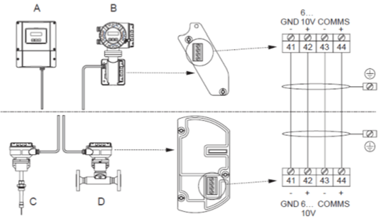
Installation methods
- A: Wall-mounted instrument housing connection, suitable for non-hazardous areas and Zone 2.
- B: Area housing, Zone 1 sensor connection housing cover.
- C: Remote insertion sensor.
- D: Remote flange sensor.
Correspondence between colors and terminal numbers
| Terminal No. | Color |
|---|---|
| 41 | White |
| 42 | Brown |
| 43 | Green |
| 44 | Yellow |
IV. Transmitter Wiring
Transmitters are available in two forms: aluminum housing and wall-mounted instrument. The wiring method is similar, but the housing structure is different.
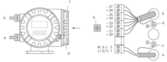
Aluminum housing transmitter wiring
Maximum cable cross-section 2.5 mm².
- a. Power supply cable: 85 to 260V AC, 20 to 55V AC, 16 to 62V DC. Terminal No. 1: AC L1, DC L+; Terminal No. 2: AC N, DC L-.
- b. Signal cable: Terminal Nos. 20-27.
- c. Protective ground terminal.
- d. Ground terminal for signal cable shielding.
- e. Service interface: connect Fieldcheck, FieldCare.
- f. Terminal compartment cover.
- g. Hexagon socket screw cover lock.
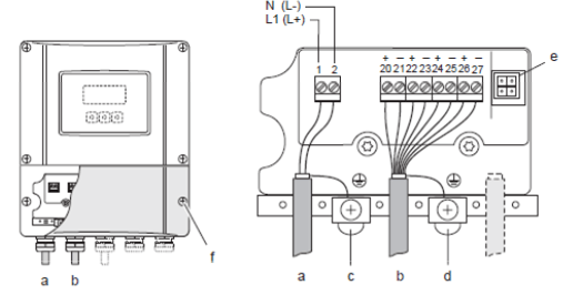
Wall-mounted instrument transmitter wiring
Maximum cable cross-section 2.5 mm².
- a. Power supply cable: 85 to 260V AC, 20 to 55V AC, 16 to 62V DC. Terminal No. 1: AC L1, DC L+; Terminal No. 2: AC N, DC L-.
- b. Signal cable: Terminal Nos. 20-27.
- c. Protective ground terminal.
- d. Ground terminal for signal cable shielding.
- e. Service interface: connect Fieldcheck, FieldCare.
- f. Terminal compartment cover.
V. Terminal Assignment
Terminal assignment determines the input/output signal type and electrical characteristics and must be configured according to the actual application.
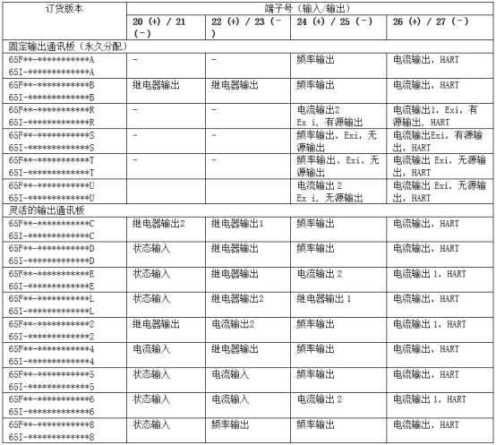
Output signals
Current output
- Active/passive output selectable, electrically isolated.
- Time constant selectable (0.0..100s), full scale value adjustable.
- Typical temperature coefficient: 0.005% o.f.s./°C, resolution 0.5 μA.
- Active signal: 0/4...20mA, RL < 700Ω (HART: RL ≥ 250Ω).
- Passive signal: 4...20mA; supply voltage Vs is 18...30VDC; Ri ≥ 150Ω.
- When the current output is configured as a temperature output, please comply with the requirements of EN 60751.
Pulse/frequency output
- Active/passive output selectable, electrically isolated.
- Active signal: 24VDC, 25mA (within 20ms, max. 250 mA), RL > 100Ω (replaceable communication module I/O, terminal assignment).
- Passive signal: open collector, 30VDC, 250 mA.
- Frequency output: cut-off frequency 2..1000Hz (fmax=1250Hz), on/off ratio 1:1, maximum pulse width 2s, time constant selectable (0.0...100s).
- Pulse output: pulse value and pulse polarity selectable, pulse width adjustable (0.05..2000 ms, factory setting 20 ms).
Switch output
- Relay output: normally closed (NC) or normally open (NO) contact selectable (factory setting: relay 1 is NO, relay 2 is NC).
- max. 30V/0.5A AC; 60V/0.1A DC, electrically isolated.
- Can be set to: fault message, limit value.
Input signals
Current input
- Active/passive input selectable, electrically isolated; resolution 2μA.
- Active signal: 4...20mA, Ri ≤ 150Ω, Uout = 24VDC, short-circuit protection.
- Passive signal: 0/4...20mA, Ri ≤ 150Ω, Umax = 30V DC.
- Can be set to: excitation meter, gas analyzer.
Correct wiring is the foundation for stable operation of the T-mass 65. Please be sure to refer to the nameplate and terminal compartment markings and complete the installation in conjunction with this guide. If you have any questions, please contact Endress+Hauser technical support.