
FMI51 Capacitive Level Transmitter Installation Precautions
Correct installation is the prerequisite for ensuring the measurement accuracy and long-term stability of the FMI51 capacitive level transmitter. The following explains four aspects: probe installation, process connection, housing adjustment, and special working conditions.
Probe Installation Requirements
The selection of probe position directly affects measurement reliability, and the following principles must be followed:
- Do not install in the feed area to avoid medium impact interfering with measurement.
- The distance between the probe and the vessel wall must be ≥50 mm, and the distance from the vessel bottom must be ≥10 mm to avoid capacitive interference.
- In stirred tanks, a safe distance from the agitator must be maintained to prevent mechanical damage.
- When lateral loads are present, a rod probe with a grounding tube must be used (Figure 4.2.1).
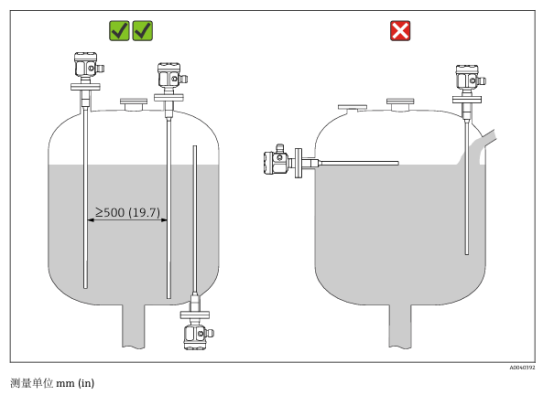
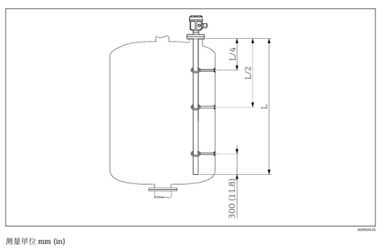
When the probe length is >1 m, a support device must be used:
- Fully insulated probes can be installed on conductive or non-conductive supports; partially insulated probes require insulation treatment of the uninsulated end.
- Support spacing: the lowest support must be 300 mm from the probe end, and intermediate support spacing must be L/2 (Figure 4.2.2).
Process Connection and Sealing
The process connection must ensure reliable sealing and avoid insulation interference. The key points for different connection methods are as follows:
- Threaded installation (G½/G¾/G1/G1½): Use elastic fiber sealing rings (chemical corrosion resistant), and torque must be controlled according to specifications (e.g., G½ ≤80 Nm). Tapered threads (NPT) require conductive sealing material to avoid insulation interference.
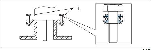
- Flange/clamp installation: Sealing rings must withstand process temperature and pressure (PTFE-lined flanges require spring washers). Regularly check screw tightening; recommended torque is 60–100 Nm.
Housing Adjustment and Sealing
The housing can be rotated 270° relative to the cable entry position. For outdoor installation, the cable must be bent downward and secured with cable ties to prevent water ingress.
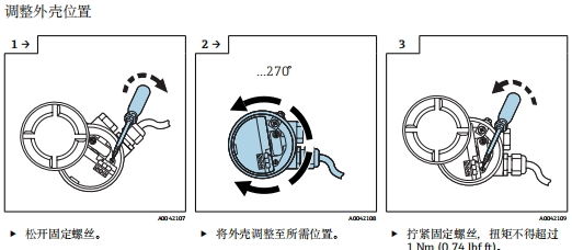
Sealing protection key points:
- Do not use mineral oil-based grease on the O-ring to avoid damaging the seal.
- After installation, confirm that the protective cover and cable gland are fully sealed to meet waterproof and dustproof requirements.
Special Working Condition Handling
For non-conductive media or remote housings, additional measures must be taken:
- Non-conductive media (conductivity <1 μS/cm): A grounding tube must be used, and the minimum probe length must be calculated according to the formula (see Section 4.4).
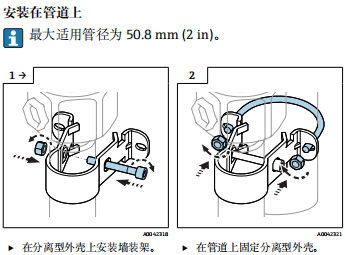
- Remote housing: The cable length between the probe and the housing must be ≤6 m, and wall-penetrating routing must be isolated from the process connection. When installing with a wall mounting bracket, it must be pre-positioned as a drilling template (Figure 4.5.2).
FMI51 Capacitive Level Transmitter Wiring Precautions
Wiring quality directly affects signal stability and explosion-proof safety. The following explains safety preparation, equipotential grounding, terminal assignment, and explosion-proof requirements.
Safety Preparation
The following checks must be completed before power-on:
- Supply voltage must match the nameplate: non-explosion-proof area 12–36 VDC, intrinsically safe area 12–30 VDC.
- Disconnect power before operation; in explosion-proof areas, the Safety Guide (XA document) must be observed.
Equipotential and Grounding
Correct equipotential bonding and grounding are key to interference resistance:
- Equipotential bonding: The cable shield on the sensor side must be grounded at one end (for explosion-proof applications). The housing grounding terminal (T13/F13, etc.) must be reliably connected to the plant grounding system (Figure 5.1.1).
- Cable specifications: Use shielded instrument cable (cross-section 0.5–2.5 mm²). When equipotential bonding is implemented, the shield can be grounded at both ends to optimize immunity (EMC compliant with NAMUR NE21).
Terminal Assignment and Connection
Two-wire wiring and M12 connector methods are as follows:
- Two-wire wiring: Terminal assignment is brown wire (+), blue wire (–) (Figure 5.2.2). HART communication requires an external 250Ω resistor (if not integrated in the power supply unit).
- M12 connector: Wiring can be done without opening the cover (Figure 5.1.4).
Special Requirements for Explosion-Proof Areas
The following regulations must be strictly observed in explosion-proof areas:
- Cable gland selection: Only specified explosion-proof cable glands may be used (see Section 5.1).
- Post-wiring inspection: Confirm correct terminal sequence; cable gland sealing is intact, and the housing protective cover is fully tightened; after power-on, a flashing green LED indicates normal operation.
Commissioning and Maintenance Related Key Points
After installation and wiring are completed, the following related matters must be noted during commissioning and maintenance:
- Calibration prerequisites: When the medium conductivity is <100 μS/cm, the tank wall distance is <250 mm, or a custom range is required, recalibration is mandatory (Section 7.3).
- Functional safety test (Position 6): After startup, a 4–22 mA ramp signal is output (about 40 seconds), and coordination with the process side is required (Section 7.2.8).
- Maintenance warning: For explosion-proof instruments, only original spare parts are allowed. After repair, the calibration values must be transmitted via the DAT module (Section 10.3).