Promass 40/80/83 Flowmeter Installation Guide
I. Basic Installation Requirements
The measurement accuracy of the Promass 40/80/83 series mass flowmeters is minimally affected by installation conditions, but basic installation specifications must still be followed to avoid measurement tube deformation and external vibration interference. Before installation, check pipe alignment and ensure flanges are properly aligned and supports are secure.
- The centerlines of the pipes before and after the flowmeter should be aligned, on the same horizontal line with no offset in other directions.
- Flanges welded on the upstream and downstream pipes should face each other correctly, with no offset in flanges or flange holes.
- Good support is recommended for the pipes before and after the flowmeter to prevent pipe vibration from affecting measurement.
- If the sensor is too heavy, appropriate brackets should be used to support and protect the piping.
As long as cavitation does not occur, measurement is not affected by valves, elbows, tees, or other fittings. However, during installation, these fittings should be kept as far away as possible, especially downstream of shut-off valves and pumps.
II. Installation Location Selection
Entrained air bubbles in the measuring tube can cause measurement errors, so the following installation locations should be avoided:
- The highest point of the pipeline, which can cause air accumulation.
- Directly at the outlet of a downward vent pipe.
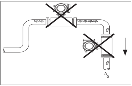
It is recommended that fluid flows through the flowmeter from bottom to top. When the flowmeter is installed on a downward pipe (such as in batching control) and fluid flows from top to bottom, a restriction orifice plate smaller than the nominal pipe diameter should be installed in the pipeline to prevent the measuring tube from being emptied.
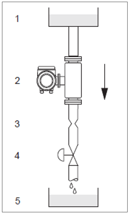
In the figure: 1 = supply tank, 2 = sensor, 3 = restriction orifice plate, 4 = valve, 5 = batch storage tank.
III. System Pressure and Cavitation Protection
Ensuring no cavitation occurs is critical, as cavitation can affect measuring tube vibration. Under normal conditions, no special measures are needed when measuring fluids with properties similar to water. However, for low-boiling-point liquids (such as hydrocarbons, solvents, liquefied gases) or in suction pipelines, the system should have sufficiently high pressure.
- Ensure pressure is not lower than vapor pressure, i.e., the liquid will not boil.
- Ensure the liquid does not vaporize.
The optimal installation locations for the sensor are:
- Downstream of the pump (to avoid vacuum).
- At the lowest point of a vertical pipeline.
IV. Installation Orientation
Confirm that the arrow direction on the sensor nameplate matches the fluid flow direction.
Vertical Installation
It is recommended to have the fluid flow upward (View V), which allows entrained solid particles to settle, gas to rise through the measuring tube, and all fluid in the tube to drain completely, avoiding solid deposition.
Horizontal Installation
The measuring tube must be installed horizontally. The correct installation is with the transmitter housing facing vertically upward or downward (View H1/H2). The transmitter housing should not be in the same horizontal plane as the pipeline.
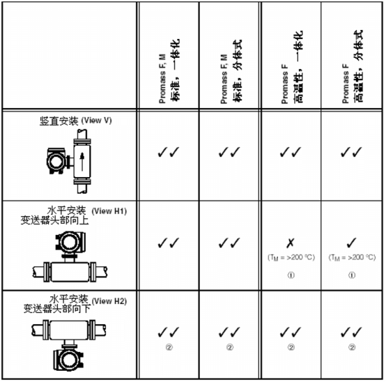
Legend: V V = recommended installation position; V x = recommended in certain cases; x = not allowed installation position.
To ensure the transmitter's ambient temperature is within the range of -20°C to +60°C, the following installation positions are recommended:
- High-temperature fluids (>200°C): horizontal installation with transmitter head facing downward (View H2) or vertical installation (View V).
- Low-temperature fluids: horizontal installation with transmitter head facing upward (View H1) or vertical installation (View V).
Special Installation Instructions
The measuring tubes of Promass F/E/H are all slightly bent tubes, and fluid characteristics must be considered during horizontal installation.
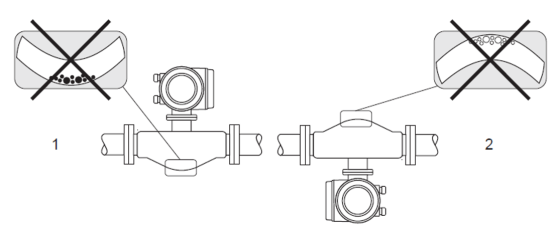
- Not suitable for fluids with solid particles, to prevent solid particle accumulation.
- Not suitable for fluids with gas evolution, to prevent gas accumulation.
V. Heat Tracing
Some measurement media require reduced heat loss at the sensor. Electric heat tracing can be used, or copper tubes carrying hot water or steam can be used to trace heat on the sensor.
Note: The electronic components of the flowmeter must not overheat! In addition, the connecting parts between the remote sensor and transmitter housing, as well as the terminal compartment, do not require insulation. Pay attention to the fluid temperature requirements for installation orientation.
- When the medium temperature is between +200°C and +350°C, heat tracing is not allowed for high-temperature integrated flowmeters.
- When electric heat tracing is used, controlling heat via phase control or pulse modulation cannot eliminate the influence of magnetic fields on the measurement value, e.g., when the measurement value exceeds the standard allowable value (Sinus 30 A/m). In such cases, the sensor must be magnetically shielded.
- For steam tracing with additional insulation in cold regions, it is best to maintain a gap of about 1 cm between the tracing pipe and the sensor housing. The tracing pipe should not be directly attached to the sensor.
VI. Insulation
Some measurement media require reduced heat loss at the sensor. Various insulation materials can be used for isolation.
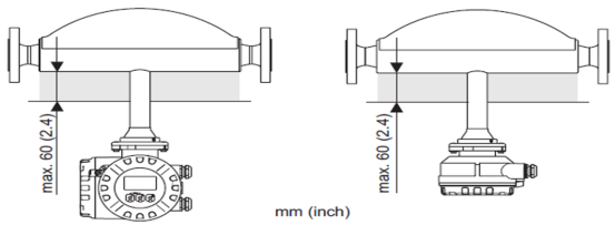
If the Promass F high-temperature flowmeter is installed horizontally (transmitter head facing upward), the minimum insulation thickness is 10 mm and the maximum thickness is 60 mm.
VII. Inlet and Outlet Straight Pipe Sections
No straight pipe section is required. However, if possible, it is best to provide straight pipe sections, especially when installed downstream of shut-off valves and pumps. Not only should they be kept as far away as possible from shut-off valves and pumps, but good support should also be provided on the pipes before and after the flowmeter. During installation, keep the flowmeter as far away as possible from valves, tees, elbows, and other fittings.
VIII. Rotating the Flowmeter Transmitter Head
When customers find it inconvenient to observe the transmitter head on site, the display head can be rotated.
Field-type aluminum housing used in non-hazardous areas
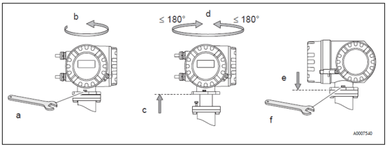
- Loosen the fixing screws.
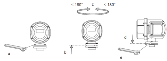
- Gently rotate the transmitter housing clockwise to the stop (top of thread).
- Rotate the transmitter housing counterclockwise (maximum 360°) to the desired position.
Field-type aluminum housing used in Zone 1 or Cl.I Div.1 hazardous areas
Rotating the field-type stainless steel housing:
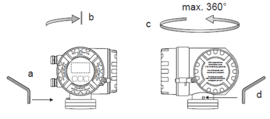
IX. Installing the Wall-Mounted Housing
1. Direct wall mounting
Confirm that the ambient temperature does not exceed the allowable range (-20 to +60°C). Install in a shaded area to avoid direct sunlight. During installation, position the cable entry downward.
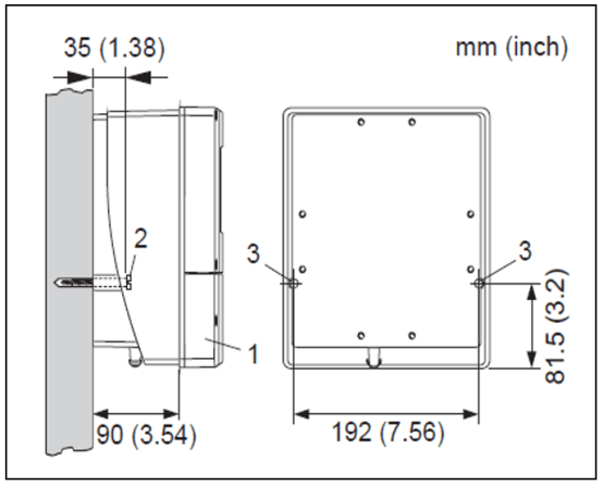
In the figure: 1. Terminal compartment; 2. Fastening screw M6: max. Ø6.5 mm (0.25"); screw head: max. Ø10.5 mm (0.4"); 3. Fastening screw mounting holes on the housing.
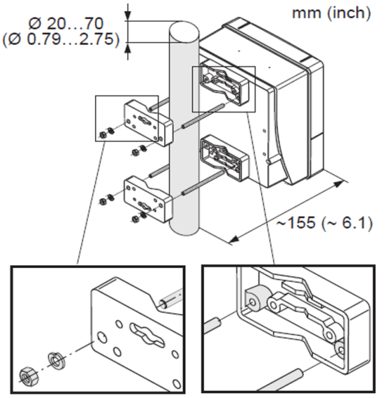
2. Column mounting dimension drawing
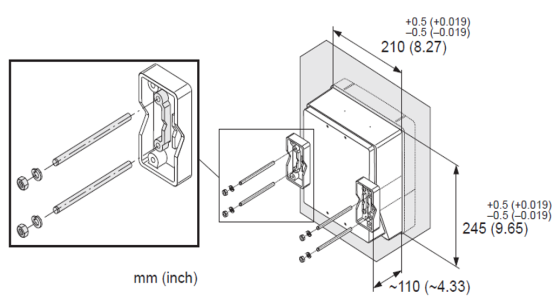
3. Panel mounting dimension drawing